What Is Rogers PCB?


Introduction
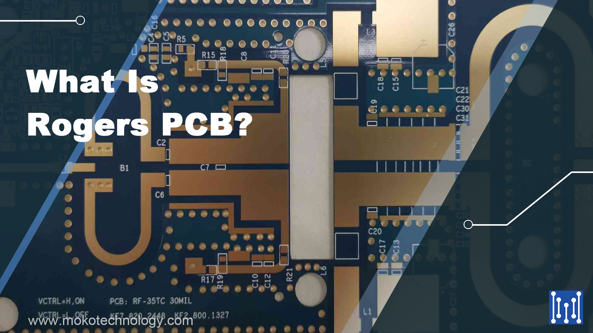
Rogers PCBs refer to high-frequency boards that are produced utilizing materials sourced exclusively from the Rogers corporation. Unlike conventional PCB boards made of epoxy resin (FR4), Rogers PCBs utilize a ceramic base as their high-frequency material, and they do not contain glass fiber in the middle. Known for their exceptional dielectric constant, low loss tangent, and high thermal conductivity, Rogers PCBs offer a range of benefits over traditional PCBs. In this blog post, we aim to provide a comprehensive introduction to Rogers PCBs, covering their unique features, advantages, applications, and more. Let’s explore the world of Rogers PCBs together…
Benefits of Rogers PCB
Rogers PCBs are a superior choice for many reasons. The Rogers material is preferred due to its exceptional ability to perform well in demanding conditions, as well as its quality and usefulness. Despite their higher cost compared to other materials, Rogers PCBs offer numerous benefit including:
- Excellent high-frequency performance with low dielectric loss
- Low Electric PCB fabrication
- Improved impedance control
- Exceptional thermal management capabilities
- Suitable for space applications with low outgassing
- Low moisture absorption and thermal expansion
- Solid dimensional stability for reliable use
- High compatibility and ease of fabrication
Rogers Types and Their Properties


In this part, we list some widely used Rogers materials with a brief introduction to their properties to help you choose the right material for your PCB project:
Rogers 3003
Rogers RO3003 serves as a popular high-frequency laminate utilized primarily for RF and microwave applications. This laminate consists predominantly of a ceramic-infused Teflon (PTFE) composite. One of its standout features is its remarkable stability in terms of dielectric constant across varying temperatures, which effectively eradicates the common issue of dielectric constant fluctuations that PTFE glass materials experience at room temperature.
Rogers 4003C
The 4003 laminate employs 1080 and 1674 glass fabrics arranged in a manner suitable for electric lamination. One noteworthy aspect of 4003C is its electrical properties, which closely resemble those of PTFE/woven glass cloth material, while its processing technology is akin to that of epoxy resin/glass cloth material. It can be effortlessly cleaned with a conventional nylon brush. The primary benefit of RO4003C is its minimal loss characteristic and the presence of two types of glass cloth.
Rogers 4350
Rogers 4350 is a high-performance material for PCB signals, composed of hydrocarbon resin/ceramic filler reinforced fiberglass, rather than PTFE. It offers cost savings compared to conventional microwave laminates as it does not require special THT through hole processing. This material has a stable dielectric constant over a wide frequency range and a low-temperature coefficient, making it an ideal substrate for broadband applications.
Rogers 4830
The thermoset laminate known as RO4830 can be fabricated using standard FR4 technology. This laminate possesses electrical properties that align closely with standard values, resulting in superior reflectance and boresight gain performance. It is particularly suitable for millimeter wave applications that prioritize cost-effectiveness, such as automotive radar sensors operating at 76-81 GHz.
Rogers 4835T
RO4835 is a specialized circuit board material developed by Rogers, which is designed specifically for inner layer design in multi-layer boards. This material is a thermoset pair that can effectively mitigate the increase in dielectric constant and dissipation factor caused by oxidation in wiring. Compared to conventional thermosets, RO4835T has remarkable resistance to oxidation, being ten times more resistant.
Rogers 5880
The Rogers 5880 High Frequency Laminate consists of a blend of PTFE composite and microfiber. Has very low moisture absorption, low outgassing, and low electrical loss. Additionally, the dielectric constant of Rogers RT/duroid 5880 laminates is very stable over a wide frequency range, making them well suited for high frequency and broadband applications.
| Rogers Materials | Dielectric Constant | Other Properties |
|
Rogers 3003 |
3.00 +/- .04.
| Dissipation factor:0.0010 to 10 GHz Substrate thickness: 0.02 “(0.5 mm) The thickness of copper: 0.5 ounces Low X, Y and Z axis CTE of 17, 16 and 25 ppm/°C, respectively |
|
Rogers 4003C
|
3.38 +/- 0.05
| Dissipation factor: 0.0027 at 10 GHz Low Z-axis coefficient of thermal expansion at 46 ppm/°C The volume resistance: 1.7×10&10 Surface resistance: 4.2*10&9 |
|
Rogers 4350
|
3.48 +/- 0.05
| Dissipation factor: 0.0037 at 10 GHz Low Z-axis coefficient of thermal expansion at 32 ppm/°C Glass transition temperature (TG) of over 280°C Surface speed of less than 500 SFM Chip Load less than 0.05 mm during perforation |
|
Rogers 4830
|
3.24 | Insertion loss : 2.2 db/in at 77 GHz UL 94 V-0 flame retardant rating Dielectric thicknesses of laminates: 0.005 and 0.0094 |
|
Rogers 4835T
|
3.3
| Density 1.92gm/cm3 Thermal conductivity 0.66w/m/k Flame retardant laminate, UL 94 V-0 rated Glass transition temperature Tg of over 280 degrees |
|
Rogers 5880
|
2.20 +/- .02
| Dissipation factor of .0009 at 10GHz Extremely low density of 1.37g/cm3 Z-axis TCDk as low as +22ppm/°C Isotropic |
Differences Between Rogers and FR4
High-Frequency
FR-4 printed circuit boards, due to their affordability, dependability, and familiar characteristics, are widely used in different applications such as audio circuits and microwave designs. Nevertheless, they are not appropriate for high-frequency applications. High-frequency-special laminates created by Rogers are the most well-known. Their materials have a dielectric constant that is about 20% lower than that of FR-4 boards. In order to evaluate whether high-frequency laminates are necessary for your project, it is important to analyze both their electrical and mechanical specifications. If the variations are too broad, it is better to use Rogers PCB material.
Dissipation
The dissipation factor or Df is an important consideration, and this factor is higher for FR-4 boards than for those made from Rogers materials. Specifically, FR-4 materials exhibit greater losses, particularly at high frequencies, with typical values of around 0.020 compared to 0.004 for Rogers boards. Dissipation in FR-4 materials also increases with frequency, whereby high-frequency laminates exhibit a consistent dissipation characteristic that is dependent on frequency. However, using FR-4 can help minimize signal loss due to its lower dissipation factor, and the automated assembly process and manufacturing of FR-4 materials make them easier to work with during assembly and production.
Impedance Stability
To ensure a steady flow of current when voltage is applied, impedance stability is important in design applications. Rogers and FR-4 are frequently utilized substances for this purpose, however, Rogers offers a greater variety of dielectric constants compared to FR-4. While FR-4 is inexpensive, its dielectric constant can vary significantly with temperature changes across the substrate. For circuits that require minimal variation over a wide temperature range, it’s advisable to use high-frequency laminates made of Rogers materials, particularly in high-temperature environments.
Dielectric Constant
The dielectric constant is the capacity of a material to retain electrical energy within an electric field. FR-4 has a lower dielectric constant of 4.5 compared to Roger’s materials, which range from 6.15 to 11. FR-4 has a higher dielectric constant than plastic materials, and using FR-4 can result in PCBs that are at least 25% lighter. FR-4 also has good moisture resistance and high dielectric strength. Although Roger’s PCBs have a higher dielectric constant than FR-4, FR-4 can still be used because it is an effective material for storing electrical energy. PCBs with higher dielectric constants are more prone to breaking when subjected to strong electric fields.
Space Application
The use of printed circuit boards in space applications is crucial, and different materials have different levels of suitability. Outgassing, which is the release of trapped gases, can be a problem in space. Moisture or corrosive materials can penetrate pinholes and damage components. FR-4 materials have good electrical stability, durability, and are cost-effective, but Rogers materials are the best for space applications due to their low outgassing and versatility.
Temperature Management
In order to regulate temperatures in electronic equipment, it is essential to utilize thermal management materials during the design process of printed circuit boards. The thermal coefficient of the dielectric constant is employed to gauge the properties of PCB materials, which can impact temperature fluctuations. Rogers materials are better for temperature management, as they have a working condition with little variation over higher temperatures. This is because they are high-frequency thermosets and more robust at higher temperatures.
Applications of Rogers PCB
Rogers PCBs find wide applications in various industries due to their superior signal performance and reliability:
- Military Devices
One of the primary applications of Rogers PCBs is in military devices, which heavily rely on signal catching and transmission. In remote areas, only high-frequency PCBs like Rogers PCBs can work efficiently to ensure uninterrupted signal communication.
- Consumer Electronics
Rogers PCBs are also used in consumer electronics such as smartphones, tablets, PCs, and laptops that require strong signal reception and transmission. Premium smartphone brands often use Rogers PCBs in their devices to ensure high-quality signal performance.
- Telecommunication
Telecommunication systems also rely heavily on Rogers PCBs for efficient signal catching and transmission. Using any other PCB could result in lower signal quality, affecting the performance of the system.
- Microwave Boards
The high-quality construction of Rogers PCBs also makes them suitable for use in manufacturing microwave boards, which are used in various industries such as cellular base stations, communication systems, and 5G stations.
- Automotive
Rogers PCBs are also used in the automotive industry for automated/mechanized test equipment, automotive radar, and sensors. RF engineering applications include power amplifiers, RF identification tags, and IP infrastructure.
- Aerospace
In aeronautic engineering, Rogers PCBs find use in aircraft collision avoidance systems, microstrip antennas, and backhaul radios.
Summary
Choosing the appropriate material for your printed circuit board is a crucial decision that will impact its suitability for specific applications. Through this blog post, we aim to enhance your understanding of Rogers PCBs. If you require further information or guidance on selecting the most suitable PCB for your project, please don’t hesitate to contact us. MOKO Technology is a leading PCB manufacturer in China with a team of experienced engineers who collaborate with clients throughout their projects. We offer assistance with material selection, PCB design, and manufacturing and assembly processes.
Recent Posts
Impedance Matching: A Critical Factor in High-Speed PCB Design
Impedance matching has become a cornerstone of the signal integrity in the realm of high speed PCB…
How to Clean a Circuit Board Safely and Effectively?
It is important to learn how to clean a circuit board properly if you’re working…
Counterbore vs Countersink: Which to Choose for Your PCB?
When designing PCBs, selecting the appropriate type of holes for fasteners is crucial. And much…
PCB Copper Foil: Types, Properties & How to Choose
PCB copper foil is one of the most critical materials in the printed circuit board…
MOKO Technology Launches Vietnam Manufacturing Base in February 2025
Shenzhen, China - February 11, 2025 - MOKO Technology, a leading global electronics manufacturing service…
PCB Solder Mask: What It Is and Why Every Circuit Board Needs It?
While most people focus on the components and copper traces that make up PCBs, there's…


