Through-hole components are electronic components with leads or terminals that are inserted into holes drilled in a PCB board and soldered to make mechanical and electrical connections. In the early days, THT (Through-hole technology) was the main PCB assembly technology, but as the integration level of today’s circuits continues to increase, components will become more compact, and today’s electronic engineers tend to choose smaller SMT (surface mount technology) components. But it is undeniable that THT still occupies an important place in the PCB industry by virtue of its own advantages. In this article, we will introduce through-hole components from various aspects and provide some insights on how to choose between SMD and through-hole components. Let’s continue reading to find more!
Types of Through Hole Components
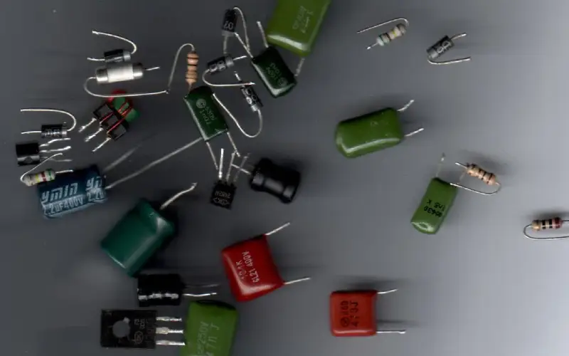
Axial lead components
Axial leaded components have leads extending from each end of the part parallel to its axis. Common examples are:
- Resistors: Through hole resistor provides resistance to the flow of electrical current and have leads at each end, making them easy to insert through holes on a PCB.
- Capacitors: Capacitors with axial leads store and release electrical energy. They also have leads at each end for through-hole mounting.
- Diodes: Axial lead diodes allow current to flow in one direction, and they typically have leads at both ends.
Radial lead components
Radial leaded parts have leads extending perpendicular to the axis of the component body. And below components often have radial leads:
- Transistors: Transistors with radial leads are used for amplification and switching. They have leads on one side of the component for through-hole mounting.
- ICs (Integrated Circuits): Some ICs come in packages with radial leads. These are less common than other IC packages but are still used in specific applications.
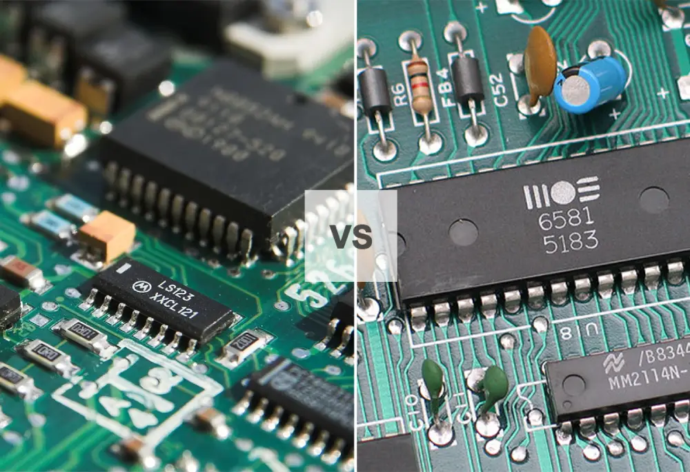
DIP ICs
Dual in-line package (DIP) integrated circuits have pin leads extending from both long sides of a rectangular plastic body. DIP ICs allow through hole soldering and breadboarding.
Pins and connectors
- Pins: Through-hole pins can be used for various purposes, such as creating test points or providing a connection between PCBs or components.
- Connectors: Through-hole connectors are used to establish electrical connections between the PCB and external devices. They come in various forms, including D-sub connectors, pin headers, and more.
Other miscellaneous through hole components include fuses, ferrite bead inductors, transformers, potentiometers, and relays. Unique geometric leads allow through hole soldering.
Read our other blog for all types of PCB components: https://www.mokotechnology.com/Circuit-board-components/
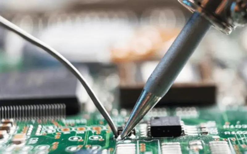
How to Solder Through Hole Components?
- Prepare Your Work Area
To get ready for soldering, first, clean the parts you’ll be joining. Use isopropyl alcohol to wash away any dirt or dust on the leads and circuit board. Let everything air dry or gently wipe with a lint-free cloth. This quick cleaning helps the solder adhere better so you can make solid, lasting connections.
- Clean the Soldering Iron Tip
Be sure to clean the tip of the iron before soldering. Heat it up, then carefully wipe it on a sponge that’s been moistened with water. This removes any oxidization or debris, allowing the iron to transfer heat efficiently for clean solders.
- Insert the Component
Insert the leads of the through-hole component into the appropriate holes on the PCB.
- Bend the Leads (if needed)
If the component has long leads, you can bend them slightly outward on the opposite side of the board to hold the component in place while soldering.
- Heat the Joint
Place the tip of the iron so it touches both the component lead and circuit board pad simultaneously. Make sure the tip contacts both the lead and the PCB pad.
- Apply Solder
Once the joint is heated (typically within 2-3 seconds), touch the solder wire to the joint. The solder should flow smoothly around the joint and cover both the lead and the pad. Do not apply too much solder; a small amount is usually sufficient.
- Remove the Solder and Iron
Once the solder flows, first pull back the wire, then the iron. Keep the joint motionless for a few seconds as the solder hardens and sets. This cooling time is crucial for creating a strong, lasting connection between the parts. Don’t move the component or the board until the solder sets to avoid creating “cold joints.”
- Inspect the Joint
Visually inspect the solder joint to ensure it appears shiny, smooth, and evenly distributed. A properly soldered joint should have a concave, slightly raised appearance.
- Trim Excess Leads
If needed, use flush cutters to trim any excess component leads flush with the PCB. When trimming excess leads, leave a bit of space between your cut and the solder joint. Getting too close risks damaging the connection you just made.
- Repeat the Process
Repeat steps 3 to 9 for each through-hole component on your PCB.
- Clean the PCB (optional)
Once all soldering is complete, consider tidying up the board. Use isopropyl alcohol and a small brush or cotton swab to gently remove any leftover flux. This removes debris and leaves the solder joints and circuit board clean.
- Test the Circuit
Before closing the device or powering it up, double-check your solder joints and ensure there are no solder bridges or shorts.
Tips for Handling Through-Hole Components in Your PCB Design
Here are some tips for effectively incorporating through hole parts in your next board layout:
- Evaluate where through hole components make sense – Consider factors like cost, assembly time, replacement needs, and vibration resistance. Through hole may be preferred for connectors, power devices, or critical components.
- Get the hole size right – Follow manufacturer specifications for drill diameter. Too small increases resistance, and too large can impact solder joint quality. Remember pads are larger than holes.
- Mind the spacing – Leave adequate spacing between holes and traces for routing. Components like DIP ICs require higher hole densities. Consult datasheets.
- Corner the market on stability – Place through hole parts near the corners and edges of boards whenever possible. This provides more mechanical stability.
- Simplify soldering – Design boards so through hole leads accessible from one side only. This prevents “shadowing” while soldering.
- Plan for securing – Consider adding board mounts, brackets, or other holding points if through hole parts are large or heavy.
- Protect hole plating – Specify plated through holes or edge plating. Avoid exposing untreated laminate material to prevent oxidation.
SMD VS Through Hole Components
Difference between SMD and Through Hole Components
SMD (surface mount device) components have leads that connect directly to the surface of PCBs rather than through holes. And though hole components differ them from:
- Different packaging
With SMT parts, leads are soldered directly to metallic pads on the board surface. No holes are needed, eliminating drilling. The pads are defined in the PCB layout to match the component’s lead configuration. SMT pads are typically created using panel plating or pattern plating processes. Through-hole parts require holes to be mechanically drilled through the entire board layer stack. The leads are inserted into the holes and soldered. Plated through-holes (PTHs) then connect pads on both sides through the hole walls. PTHs allow access to solder and inspect joints from both sides.
- Different assembly methods
SMT mounting leverages high-speed pick-and-place machines to precisely position components on pads. Parts are handled by small vacuum nozzles and rapidly populated across the PCB surface. Reflow soldering then solders all pads simultaneously. The entire process is highly automated with great efficiency.
Through-hole component insertion, in contrast, is a sequential process. Leads must be oriented and inserted into corresponding holes. Automated insertion machines exist but operate at slower speeds than SMT pick-and-place. They are also limited to components with consistent lead spacing. Irregular through-hole parts often require manual insertion by operators using tools like tweezers.
- Different soldering methods
SMD soldering is done using reflow ovens that uniformly heat the entire circuit board. The board passes through temperature controlled zones that bring all pads and leads above the solder melting point simultaneously. Solder paste between the pads and leads flows together, then cools to solidify joints. The parallel process is efficient for high volume SMT production.
Through-hole soldering is traditionally done by wave soldering or manual soldering. Wave soldering passes boards over a molten solder wave, allowing the liquid to wick into each plated through-hole. Manual soldering uses an iron or soldering station to heat individual joints for lead insertion and capillary action. Both operate sequentially on each connection.
Advantages of SMD
Smaller size – SMD components take up less space on the board.
Higher component density – More SMD components can be placed in the same footprint.
Reduced drilling – No holes need to be drilled for SMD part leads.
Automated assembly – SMDs can leverage faster pick-and-place and reflow soldering.
Performance – Eliminating lead wires improves electrical performance.
Advantages of Through Hole
Easier prototyping – Through hole parts are simpler for breadboarding and custom PCB assembly.
Withstands vibration – Leaded through hole parts can better handle vibration forces and shocks.
Visual inspection – Through hole solder joints are easily inspected from both sides.
Easier rework – Removing and replacing through hole parts is straightforward.
Considerations When Choosing Component Type
Production volume – SMD is preferred for high volume manufacturing.
Space requirements – SMD allows for smaller and more compact layouts.
Serviceability – Through hole may be required if components need replacement.
Environmental factors – Through hole withstands vibration, shock, and moisture better.
Evaluating tradeoffs like size, assembly, inspection needs, and operating conditions helps determine the best component type for the application.
Closing Words
Although through-hole parts may appear outdated, they continue to serve vital functions in modern printed circuit boards. This mature technology remains useful thanks to its simplicity and reliability. With the right design and assembly considerations, through hole parts can be effectively combined with more modern SMT components. Understanding the pros, cons, and best practices is key to making the most of through hole technology. With this summary of through-hole component basics, you now have a better understanding of how to integrate them into a printed circuit board design. Applying this knowledge can lead to more successful use of these time-tested parts in your next project.