SMD soldering refers to the process of soldering surface mount electronic components to printed circuit boards. As electronic devices and PCBs have gotten progressively smaller, the use of SMD components has skyrocketed in circuit design. The tiny size of SMD components enables far greater component density on circuit boards and allows for the miniaturization of modern electronics. However, their small footprint also creates some unique challenges for assembly and soldering. In this guide, we’ll walk through the key tools & materials, the step-by-step process for properly soldering SMD components and master SMD soldering rework.
Essential SMD Soldering Tools & Materials
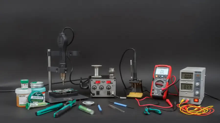
Surface mount device soldering requires some specialized tools in order to handle tiny components and make precision solder joints. Here are some of the essential items you’ll need:
Soldering Iron – A fine-tipped soldering iron in the 15-30W power range is ideal for SMD work. Tips as small as 0.5mm can be used. Temperature control features help avoid overheating.
Hot Air Soldering Gun – Use hot air to melt solder or solder paste, equipped with different gun tips.
Flux – Usually rosin solution or flux paste. Pen-type or needle-type applicators allow for better control of the amount used.
Cleaning Agent – PCB cleaner or isopropyl alcohol, usually combined with a brush or cotton swabs, is used to remove residual flux.
Solder Paste– Solder paste consists of a mixture of powdered solder alloy and flux cream. It allows solder to be precisely applied to SMD pads before components are placed.
Microscope – A stereo microscope or magnifying glasses are indispensable for inspecting small solder joints and component placement. A microscope with 20x to 40x magnification is typical.
Tweezers – Fine-tip tweezers allow precise handling and placement of SMD components as small as 0201 or 01005 sizes (0.25mm x 0.125mm). Anti-static tweezers are preferred.
Soldering Helping Hands – Helping hands tools with magnifying lenses allow hands-free positioning of PCBs under a microscope during soldering.
Stencil – PCB stencils are thin metal sheets laser-cut with a pattern of openings matching the PCB’s solder pad layout. To apply solder paste, the stencil is aligned to the PCB and the paste is screened onto the pads through the stencil’s openings. Using a stencil allows precise and efficient solder paste application prior to SMD component placement.
Jigs – Jigs help position boards at an angle which improves visibility and access to solder joints underneath components during hand soldering.
Solder Sucker/Desoldering Tools – Specialized vacuum tools are used to remove or rework solder joints and desolder components for repair work.
How to Do SMD Soldering: A Professional Step-by-step Guide
Prepare the PCB by thoroughly cleaning it to remove any debris or oxidation that may be present. You can then start SMD soldering with a soldering iron or a hot air soldering gun.
SMD Soldering with Soldering Iron
Step 1: Flux Application
Use a flux pen to evenly cover all SMD pads with flux. For leadless ceramic ICs, pre-tin pads with solder (work quickly at a moderate temperature to avoid over-melting).
Step 2: Component Placement
Use anti-static tweezers to precisely place the chip on the PCB pads. Check thoroughly to ensure that each terminal is aligned with its respective pad.
Step 3: Corner Tack Soldering
Put a little solder on the soldering iron tip to solder the diagonal corners of the chip and hold it in place. Recheck alignment before the next step.
Step 4: Flux Reapplication
Use the flux pen again to apply a fresh layer of flux over the pins and pads, ensuring smooth solder flow and preventing oxidation.
Step 5: Drag Soldering with a Mini Wave Tip
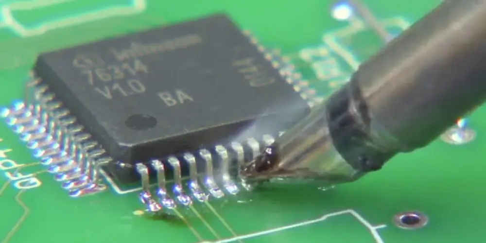
Use a mini wave tip to drag soldering, which has a solder reservoir at its head. Firstly load the reservoir with molten solder. Gently touch the outer ends of the pins and QFP pads with the tip. Slightly lift the tip by about 0.5 mm to allow molten solder to flow from the reservoir into the pad and pin area, forming a solder joint. In this step, pay attention to the hand gestures. The axis of the soldering iron tip should form an angle of 30°to 45°with the edge to be soldered. Do not drag soldering too fast, and control it to drag through one soldering point in about 1 second.
Step 6: Final Inspection & Cleaning
Once soldering, thoroughly inspect each solder joint under a microscope to check for any shorts or poor soldering that require rework. For short circuits, apply flux and re-drag (max 2 attempts per area). If the soldering is not done properly once, wait until it cools down before soldering again. (≤3 reworks total). While there are no defects, perform a clean process.
SMD Soldering with Hot Air Soldering Gun
Step 1: Pre-Soldering Inspection
Inspect the PCB pads for adequate solder bumps. If the solder amount is insufficient, apply a small amount of solder on the pads with a soldering iron. If there is no solder bump, deposit solder paste on the pads using the PCB stencil.
Step 2: Flux Application
Apply flux to both the component pins and the pads to improve adequate wetting during the reflow process.
Step 3: Component Placement
Use tweezers to position the SMD component accurately on the PCB pads. Make sure the leads are properly aligned with the pads.
Step 4: Preheating
Before soldering, use the hot air gun to gently preheat the area around the component. This prevents thermal shock and ensures even heating.
Step 5: Reflow Soldering Process
Apply hot air to the component evenly till the solder melts and reflows. For small SMD components, surface tension will help the component auto-align into the correct position. When working with QFP components, pay attention to pin alignment during heating. It’s recommended to solder one row of pins first, verify for alignment, and then solder the other rows.
Step 6: Final Inspection & Cleaning
After soldering is complete, inspect for any potential defects. Clean the circuit board with isopropyl alcohol and a brush or cotton swabs to eliminate any residual flux.
Tips to Follow During the Soldering Process
- Use the lowest effective soldering iron temperature to avoid damaging sensitive components.
- Keep the soldering tip clean between joints to ensure optimal heat transfer to the joint.
- Apply just enough solder to form a proper fillet on each joint. Insufficient or excess solder can lead to unreliable connections.
- Watch solder flow and wetting and reapply flux or pre-tin pads if needed.
- Avoid touching or bumping the PCB until all solder joints have cooled and hardened.
- Visually inspect underneath components like BGAs and QFNs if possible.
- Take ESD prevention steps like grounding wrist straps and mats.
- Work systematically from the center outwards or from small components to larger ones.
- Keep pads cool by avoiding prolonged heat in one spot to prevent pad lifting or PCB damage.
How to Do SMD Soldering Rework?
Reworking surface mount device soldering is a delicate process but an essential skill for PCB repair and modification. While great care must be taken, it is possible to successfully desolder and replace SMD components without causing board damage. We will then introduce how to do SMD soldering rework using a hot air soldering gun and a soldering iron.
Desoldering with a Soldering Iron
Apply flux on the component pins and select an appropriate soldering iron tip with 200-400℃ temperature. Heat the pins to melt the solder and remove the components with tweezers. The operation is slightly different for various types of components. The following are the specific details.
Two-Terminal SMD Components – Begin by applying solder to one end and heating it using the soldering iron. While the solder is melting, quickly heat the other end. When both ends are molten, use tweezers to remove the component. You can use two soldering irons to heat both ends at the same time.
Dual In-line Package (DIP) ICs – Apply flux to the pins, then pile solder along one row. Move the soldering iron along the row of pins to melt the solder. Insert tweezers between the IC and pads on the molten side and lift to separate the pins. Remove excess solder with a soldering iron or solder wick. Repeat the operation for the other side to remove the component thoroughly.
Quad Flat Package (QFP) ICs – Apply flux to the pins and solder wick. Place the solder wick over the row of pins and heat with a soldering iron. Insert a thin non-wettable steel shim between the pins and the pads to lift them. Repeat for all sides until the chip is off.
Desoldering with a Hot Air Gun
Apply flux on the component pins and hold the components with tweezers. Preheat the components around with a hot air gun, then blow on the components. Do not stay in one place and move the hot air gun head quickly to heat each pin. When the pin solder is melted, remove the components with tweezers. Finally, clean the pads for re-soldering.
What you should keep in mind:
-Perform the overall pre-heating, usually for 30 seconds.
-Choose the gun tip according to the shape of the component, using a tubular gun tip in general.
-Keep the gun tip perpendicular to the circuit board as much as possible and about 10 mm away from it.
-Generally, set the wind speed to 1-3 levels and heat to 5 levels.
Final Thoughts
SMD soldering can seem daunting at first due to working with ridiculously small components and joints. But with some practice, the right tools, and by following solid technique, you can successfully solder components of nearly any size. With surface mount components only getting smaller and boards more densely packed, learning SMD soldering skills is becoming a must for any PCB beginners and electronics hobbyists.