PWB vs. PCB: What’s the Difference? How to Make the Choice?


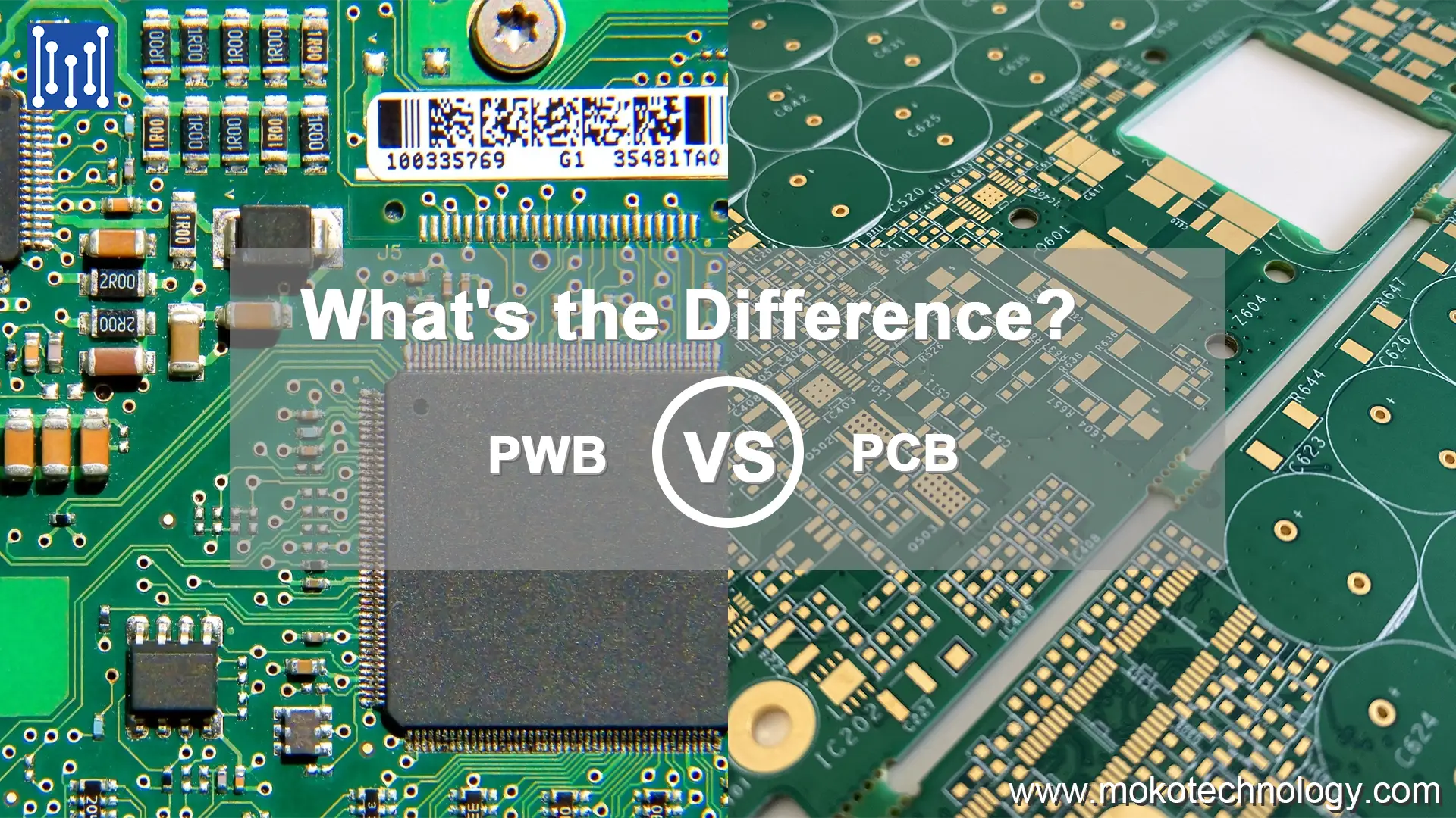
In the electronics manufacturing industry, two terms are often used: PWB and PCB. Are you wondering what is the difference between the two? What kind of connection exists? In fact, PWB stands for Printed Wiring Board and PCB stands for Printed Circuit Board. Despite the similar names, they refer to two different components that perform important functions in modern electronic devices. In this blog, we will make a detailed introduction to PWB and PCB, and compare their differences to help readers grasp a clear understanding of these two related terms.
What Is a PWB?
Printed wiring boards are the backbone of modern electronics. Without PWBs, it would be incredibly difficult to interconnect all the various components that make up an electronic device. PWBs provide a sturdy base to physically mount components. The main purpose of a printed wiring board is to create conductive tracks that allow electrical signals to flow between components so the device operates properly.
PWB is typically crafted from non-conductive substrates such as fiberglass-reinforced epoxy laminate or phenolic paper. These substrates provide both sturdy physical support and electrical isolation for circuit board components. The conductive pathways on a PWB are fashioned using conductive traces made of materials like copper. These traces are meticulously designed and etched onto the surface of the board, forming an intricate network that links different segments of the circuit.
What Is a PCB?


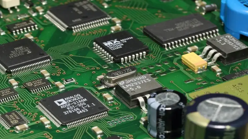
A PCB, or Printed Circuit Board, is a flat board made from a non-conductive material (usually fiberglass or composite epoxy) on which electronic components are mounted and interconnected using conductive pathways or traces etched onto the board’s surface. PCB provides the substrate on which various electronic components such as integrated circuits, transistors, resistors, capacitors, and other parts can be mounted and interconnected.
There are types of PCBs with different shapes and sizes depending on what they’re designed for. Some are simple rectangular boards with just a few components for basic devices. Others are densely packed, intricate boards crammed with components to control complex electronics like computers. The wide range of PCB designs reflects their flexible nature – they can be tailored to suit the needs of any electronic system. Compared to manually wiring everything point-to-point, PCB makes life so much easier for engineers. They allow efficient placement and routing of connections, reducing the rat’s nest of wires. And by providing a sturdy base for components, PCB also improves reliability and consistency.
Key Contrasts between PWB and PCB
- Construction and Layout
The construction methods of PWB and PCB lay the groundwork for their distinctions. PWB typically involves printed conductive paths on a substrate, focusing primarily on wiring. PCB, on the other hand, boasts a more elaborate design, incorporating layers of conductive material separated by insulating layers, facilitating a more intricate circuitry layout.
- Components and Integration
While PWB focuses on wiring, PCB harmonizes wiring and components. Electronic elements are soldered onto the board, forming a symbiotic relationship that enables circuits to fulfill their designated tasks. Printed wiring boards usually lack the integration prowess that PCB offer, limiting their capabilities in complex electronics.
- Applications and Industries
Printed wiring boards are well-suited for industries where basic electrical connectivity is the primary goal, such as in simple consumer electronics. On the other hand, printed circuit boards, with their capacity to incorporate complex components, are favored where advanced performance is required, such as in computing, automotive, and telecommunications.
- Functionality and Complexity
The most glaring distinction between PWB and PCB is the realm of functionality and complexity they encompass. Printed wiring boards serve the straightforward purpose of creating electrical connections between points in a circuit. Their focus is providing the fundamental wiring backbone to link components together. In contrast, printed circuit boards go well beyond just connecting components. PCB integrates a variety of electronic components to build complex, multifaceted circuits and systems.
This table summarizes some key distinctions:
| Characteristic | PWB | PCB |
| Substrate | Often phenolic resin or fiberglass | FR-4 fiberglass most common |
| Traces | Hand-routed or wire point-to-point | Pre-etched copper traces |
| Components | Manually soldered | Reflow or wave soldered |
| Design | Simple, customized | Complex, standardized |
| Volume | Low, prototyping | High, mass production |
| Cost | Lower | Higher setup but lower assembly |
PWB VS PCB: How to Make Choices between Them
PWB serves as a foundation for manual wiring and component connections. The flexibility to adjust or reroute wires makes PWB well-suited for prototypes or projects requiring adaptability. However, the manual process of wiring each component can consume more time and introduce concerns about reliability due to potential loose connections.
Printed Circuit Boards, on the other hand, feature components directly mounted and etched onto the board through an automated procedure, which enables more densely packed and compact layouts by eliminating the necessity for manual wiring. Nevertheless, any modifications entail replacing the entire board, thus making PCB the preferred choice for mass production or applications necessitating consistent reliability over time. Conversely, printed wiring boards offer heightened flexibility for designs of lower volume or those subject to frequent changes.
So which approach should you choose – the fixed PCB or customizable wire-wrap board? Well, it really boils down to the application and how much tweaking you might need to do later. For simple, stable circuits a PCB makes sense – just solder and go. But for prototyping new designs that change frequently, wire-wrap’s adjustability is handy. If you need to modify a circuit down the road, a PCB requires reworking or a whole new board, while wire-wrap just needs a quick reconnect. The fixed stability of a PCB versus the flexible adaptability of wire-wrap – each has advantages based on the situation. You’ll have to weigh up the needs of your specific project to decide which is the best fit.
PWB, PCB, and Other Related Terms
The terminology surrounding printed circuit boards is nuanced, with several similar acronyms used interchangeably.
PCB refers to the entire printed circuit board, including the baseboard and assembled components. PWB specifically means the bare printed wiring board without components. However, in practice, these terms are often used interchangeably, especially in the US electronics industry.
Historically, PWB was an earlier term originating from the nascent days of the technology sector. Over time, PCB became prevalent as it better characterized the board’s function of holding a complete circuit architecture. In modern Japanese electronics, PWB is preferred over PCB to avoid confusion with polychlorinated biphenyls, a toxic chemical compound.
Beyond PCB and PWB, related acronyms include:
PCBA or PCB Assembly – A fully assembled PCB with components soldered on
PWA or Printed Wire Assembly – An obsolete term for a PCBA
CCA or Circuit Card Assembly – Technically the same as a PCBA
PCA or Printed Circuit Assembly – An uncommon alternate term for a PCBA
Closing Word
Printed wiring boards and printed circuit boards represent two pivotal innovations that fueled the electronics revolution. In the early days, printed wiring boards provided a basic platform to connect electronic components with simple wired links. This allowed the first primitive electronic devices to be assembled. However, the real game-changer was the printed circuit board. By etching conductive copper tracks directly onto an insulating board, PCB enabled the integration of many more intricate connections between components in a small space. This density and complexity enabled PCB to support advanced circuit designs packed with components like transistors and integrated circuits. PCB truly catapulted electronics forward from simple circuits to the sophisticated devices that underpin modern tech. Looking back, we can see how printed wiring boards laid the initial foundations, but it was printed circuit boards that really sent electronics skyrocketing into the future. Each technology marked a key milestone along the road of progress.
Recent Posts
Impedance Matching: A Critical Factor in High-Speed PCB Design
Impedance matching has become a cornerstone of the signal integrity in the realm of high speed PCB…
How to Clean a Circuit Board Safely and Effectively?
It is important to learn how to clean a circuit board properly if you’re working…
Counterbore vs Countersink: Which to Choose for Your PCB?
When designing PCBs, selecting the appropriate type of holes for fasteners is crucial. And much…
PCB Copper Foil: Types, Properties & How to Choose
PCB copper foil is one of the most critical materials in the printed circuit board…
MOKO Technology Launches Vietnam Manufacturing Base in February 2025
Shenzhen, China - February 11, 2025 - MOKO Technology, a leading global electronics manufacturing service…
PCB Solder Mask: What It Is and Why Every Circuit Board Needs It?
While most people focus on the components and copper traces that make up PCBs, there's…


