Placa de circuito impresso (PCB) os designers muitas vezes enfrentam interferência eletromagnética ao dispor as placas. Eles devem considerar a compatibilidade eletromagnética para satisfazer as especificações do sistema. Mesmo pequenos descuidos no layout podem gerar complicações eletromagnéticas, como curtos-circuitos ou ruído EMI/RFI. É aqui que uma blindagem de PCB se torna útil!
O que é um escudo PCB?
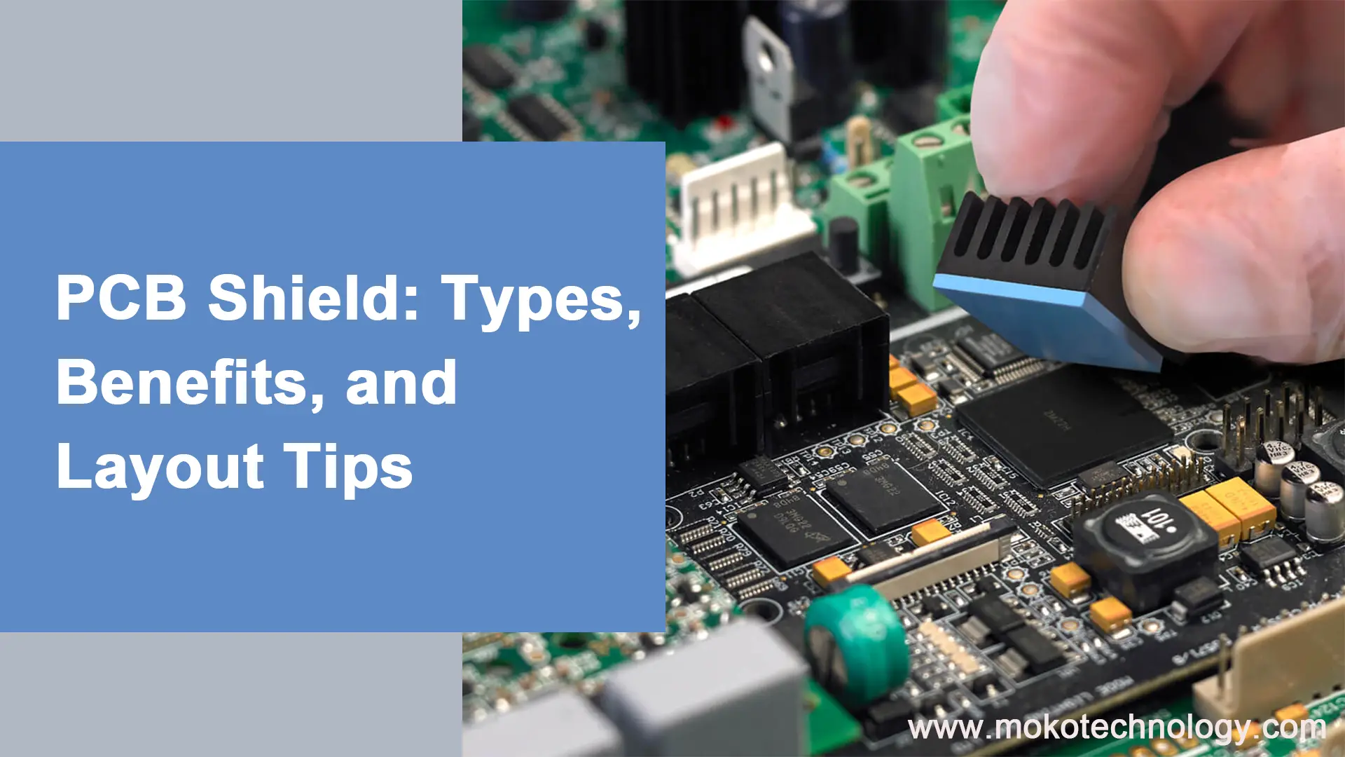
Uma blindagem de PCB é um gabinete que envolve sua PCB para protegê-la e reduzir a interferência elétrica. Geralmente é feito de um material metálico condutor que atua como um escudo eletromagnético.. Os materiais mais comuns utilizados são o alumínio, aço, e estanho.
A blindagem pode evitar curtos-circuitos, protegendo sua PCB do contato com outros componentes ou superfícies. Também protege contra poeira e detritos que podem causar curtos. Além disso, bloqueia interferência eletromagnética (EMI) de rádios, motores, e outras fontes que podem interromper seus circuitos sensíveis.
Benefícios do uso do PCB Shield
Aqui estão alguns dos principais benefícios do uso de uma blindagem de PCB:
- Evita curtos-circuitos – A blindagem evita curtos acidentais entre solda almofadas ou componentes no PCB, isolando os componentes eletrônicos.
- Reduz a interferência EMI/RFI – A blindagem eletromagnética bloqueia ruídos EMI/RFI de entrada e saída que podem interferir na operação do circuito.
- Protege dos impactos – Uma blindagem rígida ao redor da PCB ajuda a proteger contra impactos físicos, vibração, e outras tensões mecânicas.
- Contém emissões – Ele impede que a energia eletromagnética gerada pelo seu PCB irradie e interfira nos componentes eletrônicos próximos.
- Melhora a segurança – A blindagem pode reduzir o risco de choques elétricos, evitando o contato com componentes e circuitos energizados.
- Permite prototipagem – Uma blindagem permite testar e revisar com segurança o design de sua PCB com mais facilidade antes de criar um gabinete personalizado.
Tipos de blindagem de PCB
Dois métodos de blindagem predominantes são a radiofrequência (RF) blindagem e blindagem Arduino:
-
Blindagem RF PCB
A blindagem de RF bloqueia campos eletromagnéticos, cargas eletrostáticas, e ondas de rádio. As soluções comuns de blindagem de RF incluem latas de metal, materiais elastoméricos, contas e placas de ferrite, malha condutora, e planos terrestres isolados. Estas soluções funcionam como Gaiolas de Faraday, evitando que interferência externa interrompa componentes sensíveis.
-
Blindagem Arduino
Os escudos Arduino são PCBs modulares que se conectam às placas Arduino para adicionar funcionalidade. Por exemplo, sem fio, Ethernet, GSM, e escudos de prototipagem expandem os recursos do Arduino. Os pinos de blindagem conectam as placas empilháveis, evitando pinos reservados usados para barramentos I2C e SPI. Com circuitos pré-construídos e bibliotecas de códigos, Os escudos Arduino permitem implementação rápida em comparação com designs personalizados.
A blindagem RF e Arduino têm prós e contras. Os escudos de RF oferecem proteção EMI robusta, mas podem ser caros e complexos de implementar. Os escudos Arduino são acessíveis e simples, mas fornecem blindagem menos especializada. O design de blindagem bem pensado é a chave para equilibrar a proteção, custo, e complexidade para uma determinada aplicação.
Como funciona o escudo PCB?
Uma blindagem de PCB funciona contendo os campos eletromagnéticos da PCB e bloqueando EMI externo de outras fontes. O invólucro condutor forma uma gaiola de Faraday ao redor dos componentes eletrônicos, forçando o EMI a fluir ao longo da parte externa da blindagem. Isso evita interferência com componentes dentro da área blindada.
O aterramento adequado da blindagem também ajuda a absorver as emissões irradiadas e desviá-las para o solo. Normalmente são incluídas pequenas aberturas para permitir acesso aos pontos de teste, exibe, e controles. Quaisquer lacunas são minimizadas tanto quanto possível.
6 Dicas para projetar blindagem EMI em layouts de PCB
Mitigar a interferência eletromagnética em projetos de placas de circuito impresso requer técnicas cuidadosas de layout. Seguindo estes 6 estratégias principais podem ajudar a controlar a interferência eletromagnética:
- Use um plano de aterramento de baixa indutância.
Dedique uma camada inteira em placas multicamadas como um plano terrestre. Maximize a área do plano de terra para reduzir a área do circuito indutivo. Isso reduz a impedância do caminho de retorno atual, reduzindo o ruído de modo comum e as emissões irradiadas. Conecte todos os sinais diretamente ao plano de terra usando vias para evitar antenas de retorno.
- Proteger componentes sensíveis.
Use invólucros condutores aterrados em torno de componentes suscetíveis a interferências. Os campos EM induzem correntes na blindagem que cancelam os campos incidentes através de reflexão e absorção. Escolha proteção apropriada, como latas, juntas, ou telas com base na atenuação necessária.
- Impedância de controle com linhas de transmissão combinadas.
Combine a impedância de rastreamento com a impedância de origem e carga usando regras de relação largura/espaço. Isso evita reflexões e ressonâncias que causam toques e EMI. Seguir impedância controlada design em trilhas de alta velocidade. Use stubs de ajuste de impedância e resistores de terminação conforme necessário.
- Bypass de trilhos de energia com capacitores de desacoplamento.
Coloque tampas de desacoplamento de cerâmica com baixa indutância diretamente em cada pino de alimentação do IC. Isso fornece um reservatório de carga para lidar com ruídos de comutação rápida, mantendo os trilhos de energia limpos. Use vários capacitores com valores diferentes para atingir uma ampla faixa de frequência.
- Segregar e filtrar seções do quadro.
Placa divisória em analógica, digital, alta velocidade, etc e mantenha os sinais locais. Quando os sinais devem cruzar domínios, filtrar usando ferritas, bobinas e capacitores de modo comum. Contém ruído em cada seção.
- Organize o posicionamento dos componentes.
O grupo de componentes associados juntos e orientados uniformemente. Coloque circuitos digitais barulhentos longe de circuitos analógicos sensíveis. Rota traçados de forma eficiente para minimizar comprimento e cruzamento. Reduza os efeitos da antena com vias periódicas para o solo.
Aprendizado
Adicionar uma blindagem de PCB adequada ao seu projeto pode ajudar a evitar problemas de curto-circuito, Ruído EMI/RFI, e choques estáticos. Um projeto de blindagem cuidadoso é necessário para conter totalmente a interferência eletromagnética indesejada. Com blindagem robusta integrada ao layout e gabinete da PCB, você pode garantir a operação confiável de seus eletrônicos.