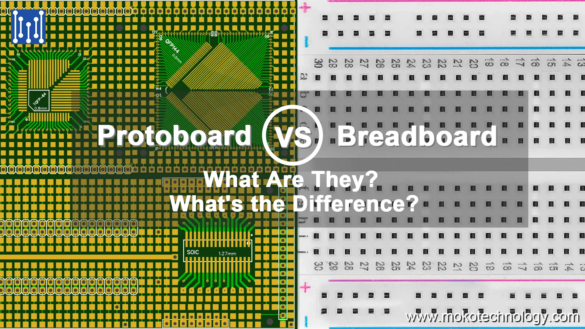

Whether you’re an electronics hobbyist or a professional engineer, sooner or later you’ll need to build a circuit. To construct that circuit and test it out, you’ll need either a protoboard or a breadboard. But what exactly are these things, and what’s the difference between them? When deciding between a protoboard vs breadboard, there are a few key factors to consider. Read on to find out.
What Is a Protoboard?
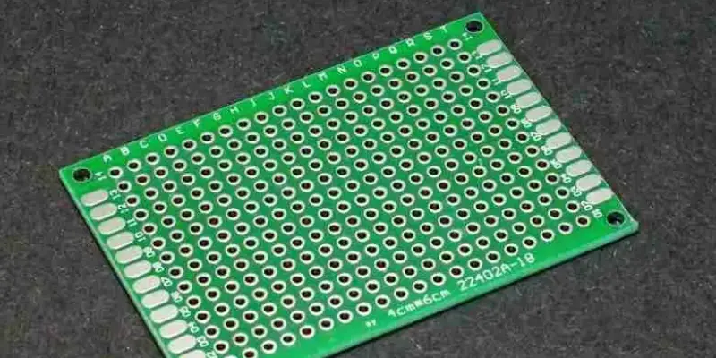
A protoboard (also called a prototyping board) is a board used to build and test out electronic circuits. It consists of a flat insulated surface with holes, solder pads, or sockets to insert components. The pads/holes are interconnected with copper traces in a pattern underneath the board.
Advantages and Disadvantages of Protoboard


- Advantages
Stable and durable connections – Soldering components to the protoboard creates robust mechanical and electrical connections that can withstand stress and last a long time.
Good for permanent projects – If your circuit design is unlikely to change much, a protoboard creates a semi-permanent solution perfect for the final project build.
Customizable layouts – Protoboards allow flexibility in component placement and routing of traces. You can optimize the layout for your specific design needs.
Handles complexity well – The stability of a protoboard is ideal for building more intricate, complex circuit designs reliably.
Cost-effective – Protoboards offer an affordable option for hobbyists and students compared to custom PCB fabrication.
- Disadvantages
Requires soldering skills – To assemble circuits on a protoboard you’ll need to know how to solder components correctly and cleanly.
Less reusable – It’s not as easy to remove/replace components on a protoboard compared to using a breadboard or stripboard.
Limited debugging – Troubleshooting malfunctions can be tricky since you can’t just plug and unplug connections to test. May require desoldering.
Lower speed – Not well suited for very high frequency PCB or RF circuits. The traces have more impedance than a PCB.
What Is a Breadboard?
A PCB breadboard is a construction base for temporary circuits, used for prototyping, testing, and experimenting with different electronics designs. The standard breadboard contains a grid of holes connected underneath by metal clips. The clips form horizontal rows and vertical columns of connected points. This allows you to insert component leads and wires to connect them up without any soldering.
Advantages and Disadvantages of Breadboard
- Advantages
Solderless – No soldering is required, just push components and wires into the holes to connect them. Very beginner friendly.
Reusable – Components can be removed and rearranged easily to modify the circuit. Great for experimenting.
Rapid Prototyping – Allows quick testing of circuit ideas by assembling temporary connections.
Visual Feedback – The layout provides a clear visualization of the circuit connections. Easy to troubleshoot.
Inexpensive – Breadboards are very affordable compared to other prototyping options.
- Disadvantages
Less Stable – The spring clip connections can loosen over time leading to faulty contacts in complex circuits.
Not Permanent – Breadboard circuits are only meant to be temporary and can’t be made into permanent projects.
Messy Wiring – Lots of jumper wires crossing over each other can make the layout confusing visually.
Size Limitations – Large or highly complex circuits may not physically fit on a breadboard.
No Mounting – Since breadboards are not soldered, they can’t be securely mounted into enclosures.
Differences between Protoboard vs Breadboard
- Connection type
Protoboards have copper traces etched on the substrate that components are soldered or pressed into. The soldering forms durable mechanical and electrical bonds, but makes altering connections more difficult. Breadboards utilize removable spring clips underneath the board to hold wires and components in place. Simply inserting leads into the holes creates temporary connections between components without soldering. This allows quick changes to be made for prototyping new designs.
- Intended use
Bread board circuits are ideal for temporary circuits like testing new prototypes where modifications may be needed. Their simplicity allows fast assembly and tweaking of designs. While protoboards are better suited for permanent or long-term circuits where reliability and ruggedness are required. The soldered connections withstand stress over time.
- Reconfigurability
Protoboard changes require desoldering and resoldering components, making modifications slower and more difficult. In contrast, breadboards enable easy component insertion/removal to reconfigure circuits by plugging/unplugging. This modifiability aids iterative design processes and experimentation.
- Layout
Breadboards have predefined internal connection patterns that can limit complex multi-component circuit designs. Protoboards offer custom layouts tailored specifically for a circuit’s needs by cutting traces and positioning components. This aids complex circuit implementation.
- Durability
PCB breadboard spring clip connections gradually loosen with repeated insertion/removal when prototyping changes. This makes them less suited for long-term use. Protoboard soldered connections withstand stress and remain robust over time and repeated circuit use.
- Cost
Breadboards are inexpensive, making them cost-effective disposable prototyping options. Protoboards have higher initial costs but can be reused for multiple projects, making them better for permanent circuits.
| Feature | Protoboard | Breadboard |
| Connection Type | Soldered copper traces | Removable spring clips |
| Intended Use | Permanent/long-term circuits | Temporary prototypes |
| Reconfigurability | Low (requires desoldering) | High (easy plug/unplug) |
| Layout | Customizable | Predefined pattern |
| Complexity | Handles highly complex circuits | Better for simpler circuits |
| Durability | Highly durable over time | Low durability long-term |
| Cost | Higher initial cost, reusable | Low cost for one-time use |
Protoboard vs Breadboard: Which One Should You Choose?
When deciding between a protoboard vs breadboard for your circuit building project, there are some key factors to consider:
First, analyze how permanent you need the circuit itself to be. If this is just for a very temporary prototype that you’ll be changing frequently and dismantling later, a breadboard is likely the best fit. Its simplicity enables you to modify connections on the fly by plugging and unplugging components as needed.
Next, examine the complexity level of your circuit design. For simpler circuits with just a few components, a breadboard can easily accommodate this. But for highly complex designs with many interconnected components and traces, a protoboard is preferable.
Also think about whether you need to precisely replicate the circuit layout multiple times, such as for manufacturing. A protoboard allows you to mimic a printed circuit board layout before fabrication.
Cost is another factor. Breadboards themselves are inexpensive, making them the most budget friendly disposable option for temporary prototyping stages.
Finally, consider how much rearranging of the circuit you anticipate needing to do. Breadboards definitely have the edge for easily modifying circuit configurations iteratively.
Final Thoughts
When deciding between a breadboard vs protoboard, it’s important to understand that both have their advantages and are extremely useful tools for electronics prototyping. Breadboards provide a quick, convenient, and budget-friendly way to test out circuit ideas. But protoboards offer more robustness, organization, and precision for complex or long-term projects. Whichever you choose, keep in mind your specific needs in terms of permanence, complexity, replicability, cost, and rearrangeability. With the right prototyping board selected for your application, you’ll be equipped to efficiently turn your innovative circuit ideas into functioning realities.
Recent Posts
Impedance Matching: A Critical Factor in High-Speed PCB Design
Impedance matching has become a cornerstone of the signal integrity in the realm of high speed PCB…
How to Clean a Circuit Board Safely and Effectively?
It is important to learn how to clean a circuit board properly if you’re working…
Counterbore vs Countersink: Which to Choose for Your PCB?
When designing PCBs, selecting the appropriate type of holes for fasteners is crucial. And much…
PCB Copper Foil: Types, Properties & How to Choose
PCB copper foil is one of the most critical materials in the printed circuit board…
MOKO Technology Launches Vietnam Manufacturing Base in February 2025
Shenzhen, China - February 11, 2025 - MOKO Technology, a leading global electronics manufacturing service…
PCB Solder Mask: What It Is and Why Every Circuit Board Needs It?
While most people focus on the components and copper traces that make up PCBs, there's…


