Things You Should Know before Starting Your PCB Design


The printed circuit board design is based on the circuit schematic and implements the functions required by the circuit designer. Printed circuit board design also called layout design, which needs to consider a variety of factors such as the layout of external connections, the layout of internal electronic components, the layout of metal wiring and Vias, electromagnetic protection, and so on. Good PCB layout design can save you production costs and improve the performance of PCBs, while poorly designed PCB may cause limited board functionality and even the failure of entire boards. So it is of great importance to make sure your PCBs are well designed, here we will explain the key steps involved in the PCB design process and some factors that should be considered before designing.
PCB Design Process


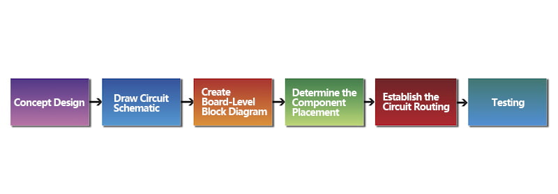
- Concept Design
The first step we need to determine the purpose of designing the PCB, which we call the conceptual design of the board. At this stage, we need to define what functions the PCB will have, what characteristics it will have, the interconnections with other circuits, the approximate size, where it will be placed in the final product, and also need to consider its operating environment including approximate temperature, humidity and so on.
- Draw Circuit Schematic
When we determine the final concept design, we will move to the next phase: draw the circuit schematic. The schematic includes all the information needed for the proper functioning of the electrical components of the circuit board including component names, values, ratings, and so on. At the same time, you should also create the bill of materials (BOM) that encompasses very detailed information such as part number, reference designator, description, quantity, package, etc, and please keep these two documents updated when every time you changed the PCB design.
- Create Board-Level Block Diagram
In the third step, we need to create a board-level block diagram, which refers to a drawing that describes the precise final dimensions of the printed circuit boards. Each area on the diagram should be clearly marked as blocks, components, and constraints.
- Determine the Component Placement
In this phase, we will decide where each component will be placed on the board. During this process, you may go through many stages of working until you make the final decision, which is quite normal. As we need to make sure that each component is placed just in the right location to maximize the quality and performance of the PCB.
- Establish the Circuit Routing
Since the position of each component is confirmed, now we need to establish the circuit routing to determine the routing and the routing priority of the circuit.
- Testing
In the last step, we need to run a series of tests to make sure that the design can meet all our needs. If the design is tested well, then we can move to the manufacturing process, if not, we need to make adjustments based on the original PCB design.
PCB Design Considerations
Board Restrictions
Board constraints, including board size and shape, need to be considered when designing a printed circuit board. First, we need to confirm that the circuit has enough space. The size of a circuit board is affected by a number of factors, such as the size and functionality of the final product. With the advancement of technology and changes in consumer demand, electronic products are becoming smaller and more versatile, which also greatly affects PCB design. Therefore, it is critical to estimate the PCB sizes before starting the design. If there is not enough space, we may need to use a multi-layer or high-density interconnect (HDI) design to achieve the desired functionality. Regarding the shape, we generally design the PCB into a rectangle, but for some products with irregular shapes, the PCB used also needs to be designed into a special shape, although it will increase the cost. Meanwhile, we need to consider the number of layers early in the PCB design. Designing a PCB with more layers increases the cost, but it allows us to design a PCB with more advanced features.
Manufacturing Processes
Before starting the PCB design, we need to consider the manufacturing process of the circuit board, as different processes have different limitations and constraints. Reference holes that work with the fabrication process on the board are needed, and we should design with components away from the PCB holes. On the other hand, we need to consider the raw materials for making the PCB and the assembly method, for instance, in some cases, they require to use both through-hole and surface-mount components at the same time. In addition, communicating with the manufacturer to ensure that they have the capability to produce the type of board required.
Components and Materials Considerations
Before starting the PCB design, we should figure out the materials and components used for the board. The design may change according to the different materials and components, and it takes some time to choose the suitable materials and components for the board. First, we need to confirm that they are available, as some materials and components are hard to find in the market. Meanwhile, we should ensure that the desired items can be got within the budget. Lastly, we also need to make sure that our designs can maximize the strengths of these materials and components.
Component Placement Order
It refers to the process that involves the order in which we place the components on the board. We recommend adding connectors and power circuits first, followed by precision circuits, critical circuits, and then other elements. During the process, we need to consider routing and generation capabilities, noise susceptibility, routing priority, and power levels. If we place the components in the wrong order may cause conflicting circuit paths or components, and we need to go back to the drawing board phase.
Placement Location
The placement of components affects the performance of the PCB and sometimes can determine the success or failure of the final product. To help you get the desired results, we suggest not placing components too close, which will bring a lot of negative effects. First, it hinders placement component automation which would cause slow testing. The machine or engineer must be extra careful when placing and testing the board if components are placed too closely. Second, it would also spend more time in the manufacturing phase, as engineers must operate slowly and carefully. It is recommended to allow at least 100 mils of space between the component and the edge of the PCB.
Orientation and Organization
When we design the PCB, we should notice that all electronic components on the circuit board should be oriented in the same direction, which can help to improve the manufacturing and assembly efficiency by eliminating any confusion, especially in the soldering process.
How to Reduce PCB Design Risks
If we can predict the possible risk, then printed circuit board design will succeed more easily. The key point to reaching the target is signal integrity in the PCB design. Let’s find out the relevant content together.
For electronic system design, the chip suppliers have finished manufacturing many product solutions including what kind of chip to use, how to build external circuits, and so on. Hardware engineers often rarely do not need to consider the principle of the circuit, they only have to make printed circuit boards on their own. However, problems would occur during PCB design, such as PCB design being out of instability, or the printed circuit board assembly boards do not work. For some large companies, many chip manufacturers will provide technical support for PCB design guidance. But some small and medium enterprises are difficult to get this support, they may make a printed circuit board prototype for times, or cost a very long time on debugging. In fact, all of this can be avoided if we understand the system design methods. Below are three skills to reduce the PCB design risk:
- Firstly, we must regard the signal integrity issues in the layout planning stage, let’s layout in this way: Is the signal properly received from one PCB to another PCB? We have to evaluate this early. It is not difficult to do only if we know a little signal integrity knowledge and awareness of the simple software operation.
- Secondly, during the PCB design process, using the simulation software to assess the specific alignmentto see if the signal quality can meet the requirements or not. The simulation process is not that complex, the key is to understand the principle of signal integrity knowledge, and use it for guiding.
- Thirdly, we must do well on risk control in PCB design. There are many problems that cannot be solved by the simulation softwareand must be controlled by the PCB designer.If we can master the PCB design tips well, it will help to reduce the failure possibility and no need to make times of PCB boards to save cost & time, also the debugging is relatively easy.
Efficient PCB Design by Using CAD
Using advanced computer-aided design (CAD) software systems helps PCB designers to avoid many layout problems and create PCBs better. Below listed some benefits that CAD can bring to us:
Semi-Automated Design Processes: CAD programs allow us to design the board by dragging and dropping components where we need them. Some CAD systems can even help us to create the traces, which also allow us to move, add or remove components or reroute as needed. In a word, by using CAD systems, we can design the PCB with high efficiency and accuracy.
Design Validation: A CAD system can be used to verify if our PCB design is valid by testing its tolerances, compatibility, component placement, and so on. Some systems can even find errors in real time that help to minimize and eliminate negative impacts before we move to the manufacturing stage.
File Generation: CAD systems can help us to generate Gerber files and other file formats needed for manufacturing, and these files generated by CAD software are featured with high accuracy.
Rule and Template Creation: We can create and store custom rule sets by using CAD programs and share them with designers to enhance the functionality of the software. Moreover, we can create templates that bring great convenience for future PCB designs.
Designing a good PCB requires a lot of expertise and experience, which is no small feat. Therefore, if you lack expertise in PCB design, it is better to ask a professional to handle it, and MOKO is your first choice. At MOKO Technology, the PCB design team with about 16 years of experience is proficient in PCB design. Our designers utilize CAD systems to efficiently and accurately design simple to complex PCBs. In addition, we provide full-scale services from PCB design to production and assembly. We have obtained certifications including ISO9001:2015, ISO14001, ISO13485, ROHS, BSCI, UL, etc., to ensure that we can always provide customers with high-quality PCBs and the best service.
Recent Posts
Impedance Matching: A Critical Factor in High-Speed PCB Design
Impedance matching has become a cornerstone of the signal integrity in the realm of high speed PCB…
How to Clean a Circuit Board Safely and Effectively?
It is important to learn how to clean a circuit board properly if you’re working…
Counterbore vs Countersink: Which to Choose for Your PCB?
When designing PCBs, selecting the appropriate type of holes for fasteners is crucial. And much…
PCB Copper Foil: Types, Properties & How to Choose
PCB copper foil is one of the most critical materials in the printed circuit board…
MOKO Technology Launches Vietnam Manufacturing Base in February 2025
Shenzhen, China - February 11, 2025 - MOKO Technology, a leading global electronics manufacturing service…
PCB Solder Mask: What It Is and Why Every Circuit Board Needs It?
While most people focus on the components and copper traces that make up PCBs, there's…


