PCB testing is a crucial step in the PCB-assemblageproces. Without proper testing, printed circuit boards may contain flaws that were overlooked during production.
Thorough testing helps catch errors and defects before the boards reach customers. This prevents field failures down the line and maintains customer satisfaction. There are several key testing procedures that should be performed to validate full functionality of both the Alleen PCB and assembled components. In deze blog, we will explain 8 types of common PCB tests, let’s check them one by one.
8 Types of Common PCB Testing Methods
Er is geen gespecificeerde methode om PCB's volledig te gebruiken en perfect te testen. Er moeten dus veel factoren in overweging worden genomen bij het nemen van een beslissing over welke methode te gebruiken. De sleutel hiervoor is om je te concentreren op de juiste testprocedures, betrouwbaarheid, en de kosten van testen. There are various methods to use in PCB board testing and designing to optimize the assembly process.
-
Controle in het circuit (ICT)
Veel PCB-fabrikanten geven de voorkeur aan één stijl van in-circuit testencircuit (ICT) of een andere. ICT gebruiken, een fabrikant zal met efficiëntie individuele elementen en hun elektronische kenmerken controleren.
Traditionele ICT heeft een “bed of nails” fixture. Deze armaturen moeten een stijlsectie hebben die bij de circuitkaart past. De armaturen komen over het algemeen terug tegen een mooie prijs. ICT blinkt het beste uit als het eenmaal wordt gebruikt voor end-of-line testen van grotendeels stabiel, producties met een hoog volume. Zodra de montage de waarde niet rechtvaardigt, makers zouden over het algemeen een aantal van de armatuurprijzen aan klanten moeten doorgeven.
-
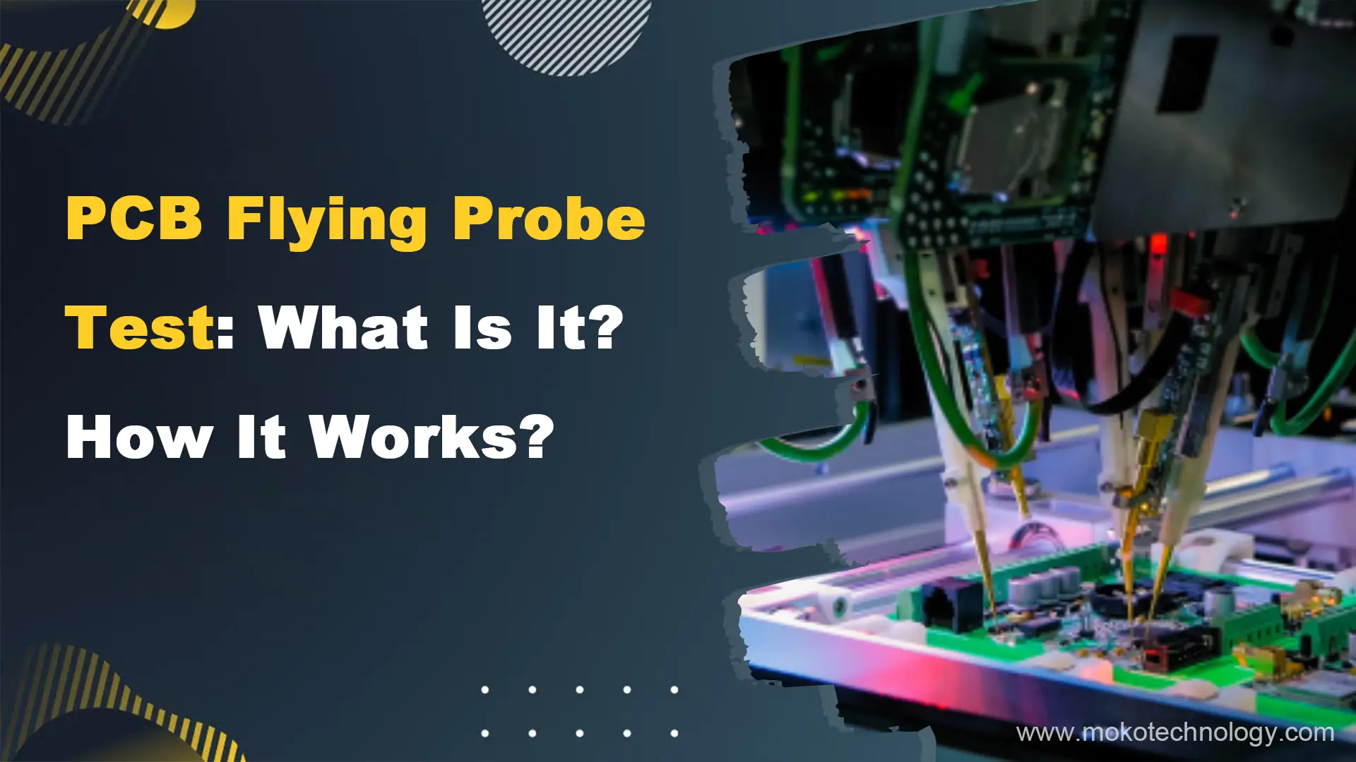
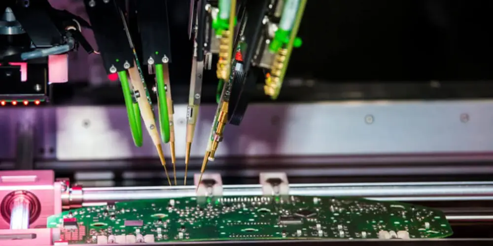
Fixtureless In-Circuit controle (FICT) / Flying Probe Test
EEN vliegende sonde-test, samen genoemd in-circuit testen zonder armatuur (FICT), is een andere stijl van ICT. Vliegende sonde elimineert de behoefte aan aangepaste armaturen, waardoor meer armatuurprijzen worden geëlimineerd. FICT gebruikt controlepinnen die ondersteunde programmering verplaatsen (vliegende sondes).
Echter, het heeft het voordeel van minder kostenberekening en, daarom, de mogelijkheid om beide zijden van een PCB te controleren. Als er een defect of nadeel aan het licht komt, het FICT-systeem hoeft alleen maar opnieuw te worden geprogrammeerd om een gloednieuw stuk te leveren, maar niet het defect? In tegenstelling tot, en ICT hebben een geheel nieuw armatuur nodig. Programmering begeleidt de vliegende sondes, waardoor het haalbaar is om tests uit te voeren die extreem specifieke gebieden en knooppunten aanwijzen. Dat nauwkeurigheidsniveau werkt goed met kleinere borden en borden met elementen met een hoge dichtheid.
-
Functionele circuitcontrole
Functionele tests gebiedseenheid dood om te certificeren dat de elektronische apparatuur functioneert in overeenstemming met stijlspecificaties. Testen wordt vaak uitgevoerd mishandeling DUT (apparaat onder test) connectoren of een BON (spijkerbed) armatuur. Een pogo pin-apparaat, een opstelling zal niet leiden tot een kortstondige associatie tussen 2 computer printplaten, wordt gebruikt om testen uit te voeren. Het aantal pogo-pinnen, soms nodig voor een praktische controle-armatuur, is aanzienlijk maar geassocieerd ICT-armatuur.
-
Grensscantesten
De grensscan kan een methode zijn voor het testen van draadlijnen op computerprintplaten. Boundary-scan wordt ook veel gebruikt als een foutopsporingsmethode om te kijken naar pinstatussen van computercircuits, spanning onder spanning, of koppel analyseer subblokken binnen een computercircuit.
-
Geautomatiseerde optische inspectie (AOI)
Geautomatiseerde optische inspectie (AOI) uses cameras to visually scan PCBs and compare to the original design files. Any deviations beyond a set tolerance trigger manual inspection. AOI provides fast defect detection to avoid continued production of flawed boards. Echter, AOI has limitations in only checking physical features without powering up components. For comprehensive testing, AOI should be paired with additional methods like flying probe, in-circuit, or functional testing to validate performance. AOI is most effective as an initial screening tool combined with electrical verification.
-
Burn-In Testing
Burn-in testing intensely stresses PCBs to uncover early defects and establish load capacity. It continuously runs power at maximum specified levels through boards for 48-168 uren. Failures during this time are called infant mortalities. For military or medical devices where reliability is paramount, burn-in testing makes sense to avoid dangerous product launches. Echter, it can shorten lifespan if overstressed. If few defects appear, the test duration can be reduced to avoid overstress. Periodic reevaluation of burn-in protocols balances reliability assurance and lifespan impact.
-
Röntgeninspectie
Röntgeninspectie, or AXI, examines PCBs for defects by producing internal images. 2D and 3D versions locate issues like poor solder joints, broken traces, and barrel cracks. 3D is faster. AXI reveals hidden flaws like under-chip ball grid array solder connections. Echter, it needs skilled operators to interpret the complex x-ray images correctly. While x-rays can penetrate multilayer boards, checking every internal layer is infeasible and costly. AXI balances defect detection and inspection time through selective imaging of critical components and layers. Periodic reassessment of AXI procedures optimizes this balance as designs evolve.
-
Visuele inspectie
Visual inspection involves thoroughly examining a printed circuit board using optical aids to check for physical defects. Inspectors look for issues like missing or damaged components, poor solder connections, contamination, assembly errors, and board damage. Magnifiers, microscopes, and imaging systems are often used to get a closer look at the PCB surface and identify flaws difficult to see with the naked eye. Visual inspection serves as an initial quality control step to catch obvious manufacturing issues before further testing procedures.
Benefits of PCB Board Testing
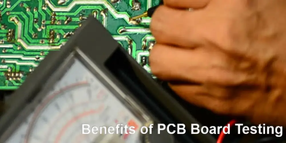
Identificatie van bugs: Het belangrijkste voordeel van PCB-testen is dat het helpt bij het identificeren van problemen in PCB's. Als het probleem in de maakbaarheid ligt:, functionaliteit, of ergens anders, PCB board testing is able to identify what is a PCB design so that designers can regulate as a result.
Tijdwinst: PCB-testen dienen als een vroeg stadium om op de lange termijn tijd te besparen. De tests stellen ontwerpers ook in staat om belangrijke problemen te identificeren tijdens de prototypingfase. In het testproces kunnen ontwerpers de oorzaak van elk probleem snel en gemakkelijk bepalengovern. Het leidt ook tot vroegtijdige beslissingen over het maken van aanpassingen, zodat ze sneller kunnen doorgaan met de productie en de productietijd kunnen beheren.
Kostenbesparing: PCB-testen spelen een sleutelrol bij het verminderen van verspillende productie van defecte producten door prototypes en kleinschalige assemblages toe te passen om de producten te testen. Wanneer testen vroeg in het ontwerpproces wordt gedaan, het helpt de ontwerpers om verspillende volledige assemblages van defecte PCB's te voorkomen. Het dient ook om ervoor te zorgen dat het ontwerp zo foutloos mogelijk is voordat het in productie gaat. Deze stap helpt de productiekosten aanzienlijk te verlagen.
PCB Testing Tools
Er zijn twee belangrijke hulpmiddelen die u kunt gebruiken om te testen of de PCB naar behoren functioneert:. Zij zijn:
- Multimeter
A multimeter is incredibly helpful for measuring voltages, current, and resistance within a circuit. It allows validation of power levels, continuity, and basic functionality. Handheld digital multimeters provide portability for testing during assembly and troubleshooting.
- Oscilloscope/Logic Analyzer
Oscilloscopes and logic analyzers visually display changing voltage over time to observe circuit operation and signals. This waveform monitoring is essential for verifying timing, speeds, lawaai, and complex interactions in digital and analog circuits. Standalone oscilloscopes are costly, but DIY options exist using an Arduino, PC soundcard, and custom circuitry to achieve basic functionality at a fraction of the price. This can be a great addition for hobbyists and students wanting to add visual testing capabilities on a budget.
Other handy test tools include clip-on ammeters to measure current draws, LCR meters to quantify inductance, capaciteit, en weerstand, and thermal imagers to check hot spots on operating boards. Building up a toolkit of testing equipment tailored to the specific PCB project enables comprehensive validation during development and troubleshooting.
Choose MOKO Technology for PCB Testing
Bij MOKO Technology, we deeply understand the importance of comprehensive PCB testing and ensure our products are rigorously validated. Met meer dan 17 years of experience in the PCB industry in China, we have assembled a veteran team of manufacturing engineers and specialists dedicated to quality assurance. Our testing capabilities cover the full range of electrical, functional, and mechanical checks needed to verify design and reliability. Voor meer informatie, contact the experts at MOKO today.