PCB and PCBA are the two most common terms in the electronics industry. Although the difference between them is only one letter, they represent different things. The full name of PCB is Printed Circuit Board, which refers to a blank board without any electronic components assembled. PCBA stands for Printed Circuit Board Assembly, which refers to a board that is assembled with various components and can achieve certain functions. PCBA is built based on PCB. In this blog, we will introduce them separately and compare their differences in detail.
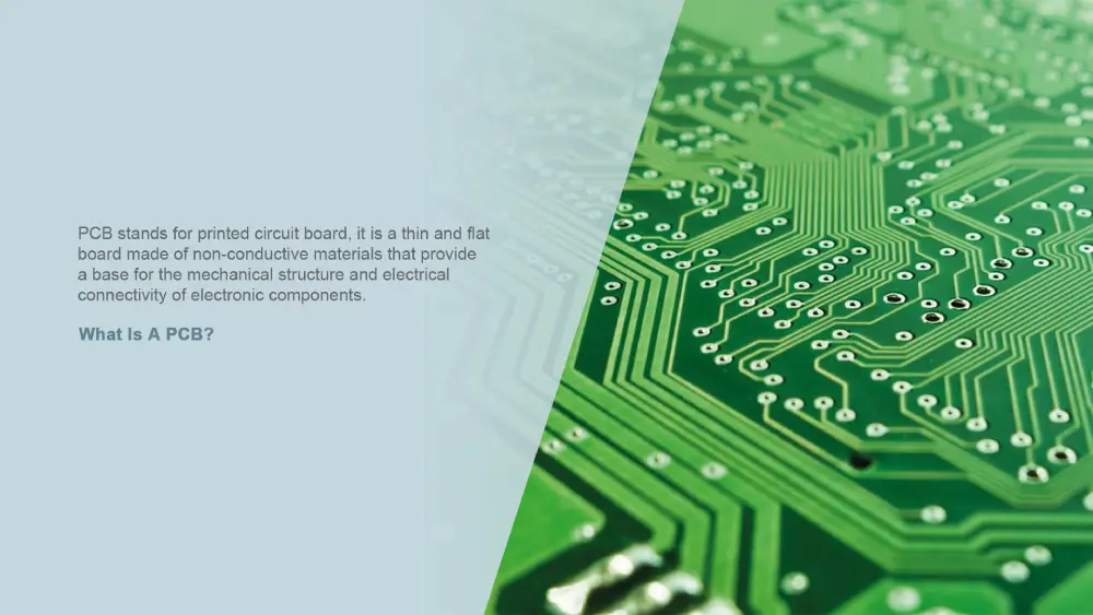
What Is a PCB?
A PCB (printed circuit board) is a thin and flat board made of non-conductive materials. It serves as a base for the mechanical support and electrical connectivity of electronic components. The PCB substrates, typically made of non-conductive materials like fiberglass or epoxy resins, allow the etching or printing of conductive copper pathways over their surface. These copper pathways are known as traces, electrically linking together various circuit board components that are soldered to the PCB.
What Are the Different Types of PCBs?
According to the number of conductive copper layers, it can be classified as:
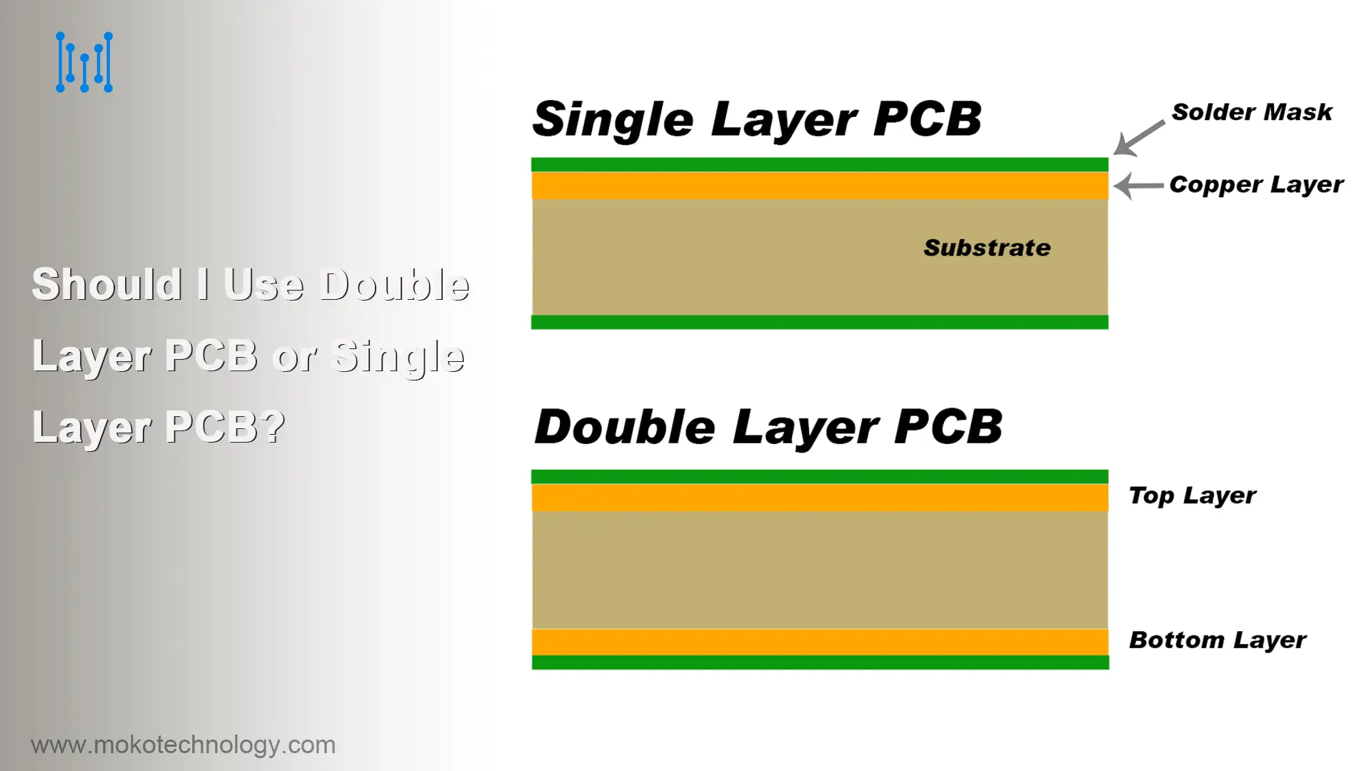
Single-sided PCBs have copper tracks on only one side of the insulating substrate, offering low-cost, simple solutions for basic circuits.
Double-sided PCBs have conductive tracks on both sides of the substrate, enabling more compact designs than single-layer PCBs.
Multilayer PCBs have multiple copper layers bonded together, allowing much denser and more complex circuitry. They are ideal for advanced electronics and allow high-speed signals.
Based on the different materials used, printed circuit boards can also be categorized as metal PCB, fr4 PCB, ceramic PCB, and so on.
To know more knowledge about PCB types, further reading: How Many Types of PCB Are There
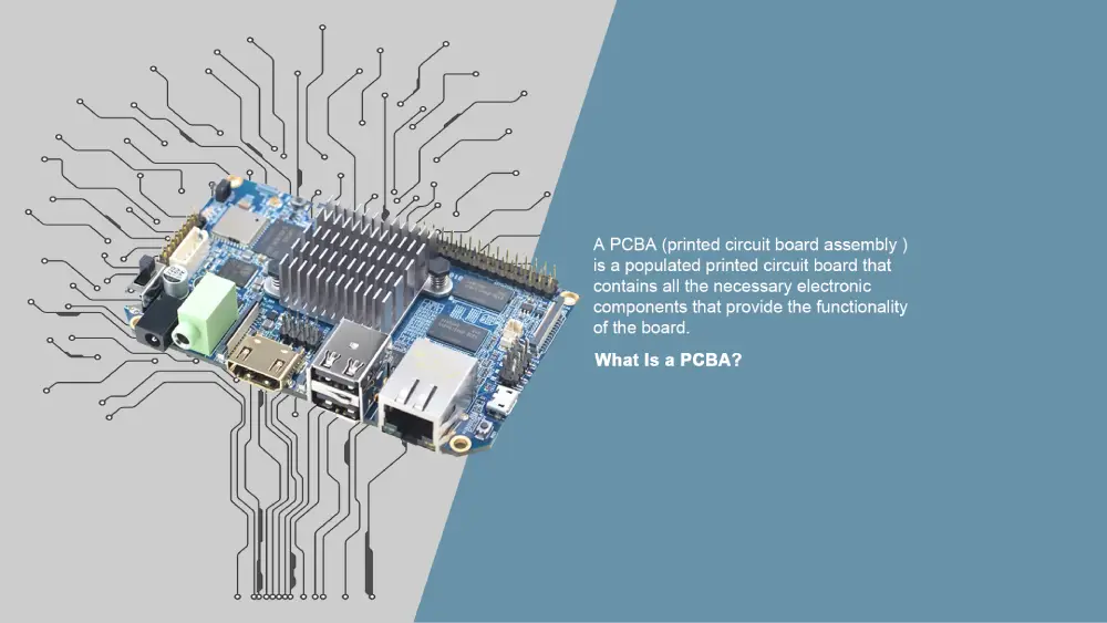
What Is a PCBA?
A PCBA (Printed Circuit Board Assembly) refers to the result of soldering all the necessary electronic components on the blank PCB, and then the assembled board becomes a fully functional circuit. In addition, it also indicates a process of installing the components on the circuit board.
Three Main PCB Assembly Methods
There are three methods that most PCBA manufacturers use for PCB assembly. The following is a brief introduction.
Surface-Mount Technology (SMT)
SMT is an automated process that can directly mount surface mount components onto the PCB surface without drilling any holes. These SMT components are small and can be packed in high density to make the circuit board compact.
Thru-Hole Technology (THT)
THT is a method of inserting components with pins into drilled PCB holes. And then the protruding leads are soldered on the opposite side. These THT components are large and require manual assembly.
Mixed-technology
Mixed technology combines the advantages of SMT and THT. It can solder small SMT and large THT components on the same PCB.
What’s the Difference between PCB and PCBA?
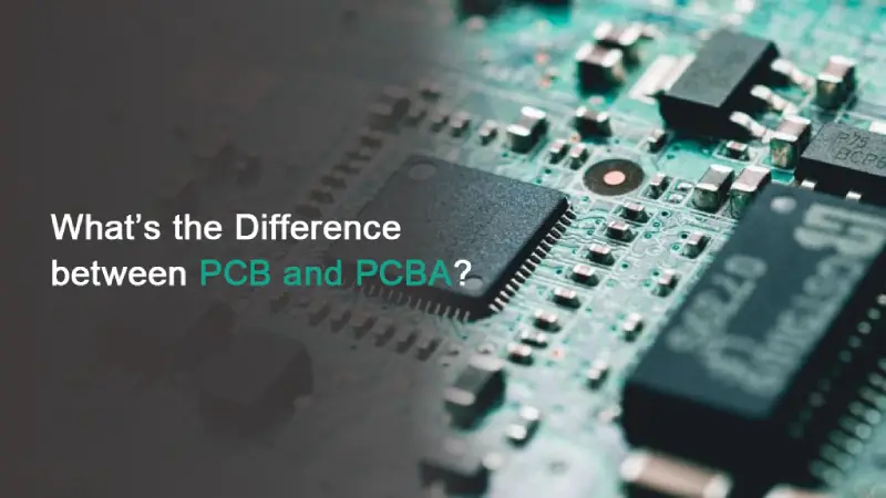
Though often used interchangeably, PCB and PCBA represent different stages in electronics manufacturing. To clear out the confusion between them, here we expound on the 5 major differences.
1. Composition and Function
As for PCB, it is mainly composed of these 4 layers:
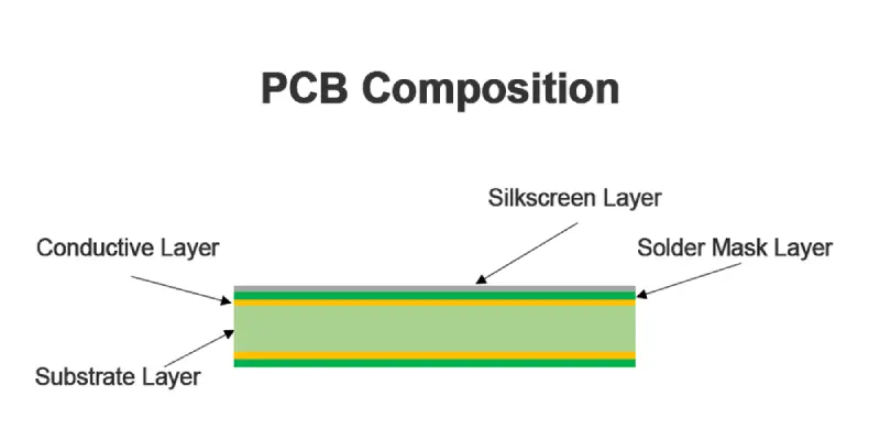
- The substrate layer is usually made of FR-4, which provides rigidity as well as insulation.
- Thin copper foil layers are bonded to the substrate to form conductive paths for the signal.
- The solder mask layer is a protective polymer coating that prevents short circuits and corrosion while leaving solderable openings exposed.
- The silkscreen layer with printed labels provides assembly and component placement instructions.
As for PCBA, it’s a complete functional unit, including:
- PCB serves as a base and is ready for installing components.
- Electronic components such as capacitors, transistors, and resistors are mounted onto the board with SMT or THT, each serving various purposes.
- Traces are thin conductive channels on the PCB surface to carry electrical signals.
- Vias are tiny holes drilled into the PCB to link various layers in multilayer PCBs, enabling signals to transmit between them.
- Solder paste forms electrical and mechanical bonds.
2. Manufacturing Process and Machines Required
Another major difference between PCB vs PCBA is their manufacturing process:
PCB Manufacturing Process
PCB fabrication revolves around crafting the bare circuit board itself. The manufacturing process is typically automated and marked by high precision, relying on specialized machines.
- Designers use PCB design software (e.g., Altium, Cadence) to assist with designing the layout.
- The unwanted copper is removed by etching machines to form traces, and copper layers are applied to the substrate by lamination presses.
- The CNC drilling machines and laser drills create vias and through-holes on the board.
PCBA Manufacturing Process
PCBA takes the PCB as its starting point to populate electronic components. This assembly process can be manual or automated, requiring different equipment to mount components efficiently.
- Solder paste printers apply precise amounts of solder paste onto PCB pads.
- Automatic and high-speed pick-and-place machines apply the SMD components with high precision using robotic arms.
- Reflow ovens melt the solder paste in a controlled thermal profile, solidifying strong connections. The wave soldering equipment is utilized for through-hole components.
3. Defects
Since the manufacturing processes of PCB vs PCBA are different, the potential defects they encounter also vary. PCB may come with these defects: excess or missing copper, over or under-etching, missing drilled holes, opens and shorts. PCBA may meet potential defects like missing or misaligned components, excessive solder, solder bridging, etc.
4. Testing
A bare PCB must undergo electrical verification before assembly. The fixture test involves using a special bed-of-nails fixture with probes to precisely connect to the test nodes on the PCB to test the circuit. It can also be used to test PCB pads, which is a more efficient testing method. In the flying probe test, the test points are contacted by a movable and flexible probe.
A PCBA needs to check components, soldering, functionality, and long-term reliability. In-circuit test (ICT) is used to detect PCB components through a fixture, easily checking manufacturing failures. The flying probe test can also be used to detect PCBA. Functional test simulates the actual working conditions of PCBA to test whether it can operate normally. The aging test simulates the long-term and periodic operation to evaluate its durability and stability. A harsh environment test exposes the assembled board to extreme temperature, humidity, drop, or vibration.
5. Production Time and Cost
PCB fabrication is generally more cost-effective and time-efficient compared to PCB assembly. PCB costs are lower due to simpler design and material expenses. PCBA involves higher costs for components and labor-intensive assembly processes. Additionally, PCBA lead times are longer due to the component integration and extensive testing required.
| Aspects | PCB | PCBA |
| Definition | A bare circuit board without components | A fully assembled circuit board with all required components |
| Components | None | All necessary components are assembled |
| Function | As the foundation for electronic component assembly | As a complete electronic module ready for operation |
| Manufacturing Process | Designing PCB layout, etching copper traces, adding insulating layers, and drilling holes | Applying solder paste, component placement, and soldering |
| Machines Required | Design software, etching machines, lamination presses, CNC drilling machines, and laser drills | Solder paste printers, pick-and-place machines, reflow ovens, and wave soldering machines |
| Assembly Techniques | Not needed, as no components are installed | SMT, THT, and mixed technology |
| Packaging Methods | Vacuum packaging | Packaging with compartments or anti-static packaging |
| Manufacturing Defect | Excess or missing copper, over or under-etching, missing drilled hole, opens and shorts | Missing or misaligned components, excessive solder, solder bridging |
| Testing | Fixture test, flying probe test | ICT test, Functional test, flying probe test, aging test, harsh environment test |
| Cost | Lower | Higher |
| Lead Time | Shorter | Longer |
| Use | Used for prototyping | Used in final electronic products |
Applications of PCB and PCBA
Consumer Electronics – From smartphones to TVs, PCB and PCBA are almost ubiquitous today, integrating into our daily used devices.
Automotive Electronics – With the popularity of electric vehicles, PCB and PCBA have become indispensable and key parts. They play a big role in battery management, autonomous navigation, etc.
Industrial Controls – PCB and PCBA act as the “heart” of the mechanical system, providing power and control capabilities. They are widely used in smart sensors, dynamic motor drives, and programmable logic controllers (PLCs).
Medical Devices – The equipment’s accuracy and dependability are of utmost importance in the medical field. Whether it is a simple heart rate monitor or a complex MRI scanner, high-precision surgical instruments, all rely on high-quality PCB and PCBA.
Aerospace and Defense – This is a demanding field where PCB and PCBA must meet extremely strict quality and technical standards. They are often used in a variety of critical electronic systems, from cockpit instrumentation to missile guidance systems.
IoT Devices – The rapid advancement of IoT is accelerating innovation in smart homes, wearable devices, and industrial sensors. Their core is the compact PCB and PCBA, silently supporting the normal operation of these IoT devices.
PCB vs PCBA: When to Use PCB? When to Use PCBA?
The following are recommended options in different situations:
When to Use PCB:
- If you only need the foundational circuit board to build upon later, a PCB is likely suitable. It allows for customization and component integration flexibility.
- Bare PCBs make sense for low-volume prototyping.
- For simple DIY projects with few components that you want to choose yourself, the PCBs offer prototyping flexibility.
When to Use PCBA:
- If you wish to have a ready-to-go electronic assembly without needing to source and solder components, a PCBA is preferable. It can directly integrate into devices.
- For complex projects with tight timelines, PCBAs may be the best option to accelerate development and save assembly time.
- PCBAs have economies of scale, which make them ideal for mass production.
Final Words
Knowing the differences between PCB vs PCBA is very important for those working in the electronics industry. The difference among them affects many factors like production, procurement, design, and cost control. Reach out to us for specialist help in your upcoming project and also to receive assistance when determining whether you need PCB or PCBA services.
FAQs about PCB and PCBA
How are PCB, PCA, and PCBA different from one another?
PCA (Printed Circuit Assembly) is another term for PCBA, but it is rarely used. A PCA (or PCBA) is a PCB that has been filled with electrical components, and a PCB is a bare circuit board.
What makes a PCB and PCBA manufacturer reliable?
Find suppliers who have:
- Choose a manufacturer with industry certifications like UL, IPC, and ISO.
- With established technical capability like SMT, testing (AOI, X-ray), and DFM feedback.
- Committed to on-time delivery without delay.
Can I assemble components on the PCB myself?
Yes! If you are building a prototype or repairing a circuit board, you can assemble it yourself. Here is what you will require: proficient skills and the necessary tools, like a soldering iron, solder, tweezers, flux, etc.
What are the materials commonly used in PCB manufacturing?
Here are some commonly used materials suitable for different types of PCBs.
- FR-4: Most typical material, offering a low-cost solution for standard PCB.
- Polyimide: Ideal for flexible PCB or rigid-flex PCB, providing high thermal stability and flexibility.
- PTFE: Particularly well-suited for RF and microwave applications, giving low dielectric constant and reduced signal loss.