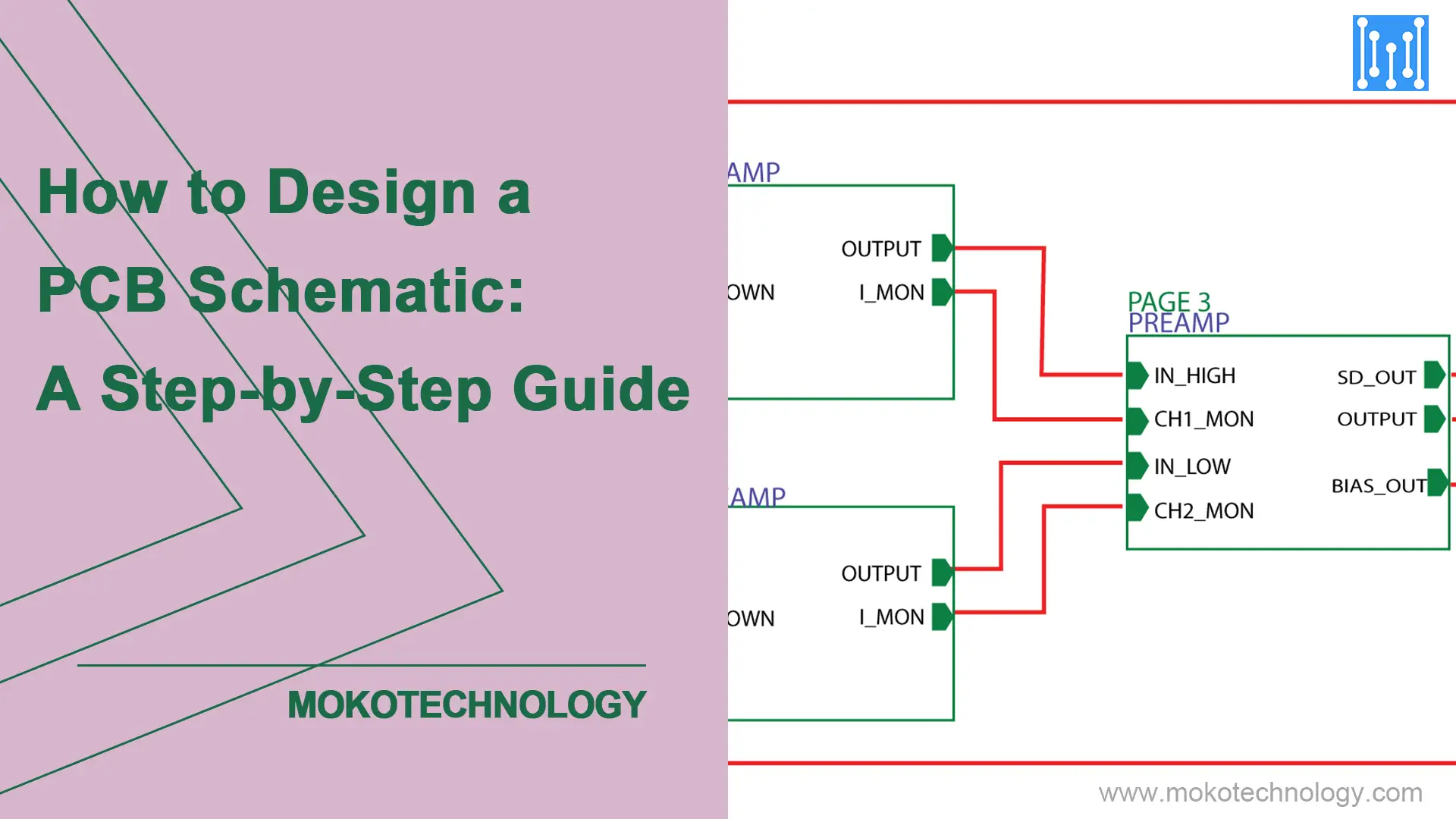
PCB 回路図: それは何ですか? どうしてそれが重要ですか?
A プリント基板設計 PCB の回路図から始まります. この PCB 回路図レイアウトは、電子回路をグラフとして視覚的に表しています。, シンボルを使用してコンポーネントを表し、線を使用して電気的接続を示します。. 通常、, PCB 回路図は物理的な基板レイアウトの前に開発されます。. 回路基板の回路図が意図した設計とプロジェクトの仕様に一致することが確認されたら, PCB レイアウトの作業と製造を続行できます. PCB 回路図により、エンジニアはさまざまなコンポーネントがどのように相互接続され、その特定の機能を理解できるようになります。. この知識は、プリント基板を修理または再生するときに不可欠です. 次のガイドでは、PCB ボードの回路図を設計するプロセスを段階的に説明します。. 読みましょう.
PCB 回路図を設計する方法?
ステップ 1: ページサイズの設定
ページの寸法を選択する際に、予想される回路図のサイズと複雑さを早い段階で評価する. 標準A4を超えて, 大きめのA3, A2 シートには、複雑な複数ページの階層にわたる数百のコンポーネントにわたる実質的な回路が収容されます。. 単純な回路が含まれている場合, コンパクトな A5 または A6 ページで十分かもしれません.
ステップ 2: ネームページ
ナビゲーション用にページ名/ページ番号をリストしたカバーシートを設定します. 基本的な機能指向の名前を割り当てることで、直感的なグループ化を実現 – “電源”, “マイクロコントローラーの構成”, “センサーインターフェース” 等. あるいは, データフローの段階ごとに分類する – 「インプット」, "処理", 「アウトプット」. 標準の英数字の順序に従い、追加のためのページ番号間の大きなギャップを避けます。.
ステップ 3: グリッドガイドラインの確立
デザイナーからの即時の要求ではありませんが、, グリッドの設定は、ツールの必要なリファレンスとして機能します. グリッドにより、コンポーネントとその接続の正確な参照が容易になります. 回路要素がグリッドに確実に密着するようにします, 検査中にシームレスなネットワーク調査を可能にする.
ステップ 4: ページのタイトルバー
回路図ページの下部にあります, フッターには包括的な詳細が表示されます. ページの寸法を含みます, ボードの評価, 改訂履歴, 回路の名前/機能, 著作権マーク, 等々.
ステップ 5: 補足メモを追加する
設計者は重要な回路メモを文書化する任務を負っています. これらのメモは、別の文書に、または回路図と並んでページに作成できます。. 特に複雑なデザインの場合, 注釈は別のページで詳しく説明されることがよくあります, ジャンパー状態や PCB レイアウト制約などの側面をカバー.
ステップ 6: リビジョン履歴を追跡する
リビジョンの追跡には、設計に加えられた変更の文書化が含まれます. 変更日も含まれます, 変更の説明, 貢献者’ と査読者’ 名前, レビューコメントも. このログは通常、回路図レイアウトの最初のページまたは最後のページに存在します。.
ステップ 7: 回路図ドキュメントディレクトリ
このディレクトリは、回路図ドキュメント内のトピックのカタログとして機能します。. 設計者が複雑な設計内で特定のモジュールを見つけるのに非常に役立ちます。. より小型でシンプルなデザインの場合, 不要と思われる場合は、この手順を省略できます.
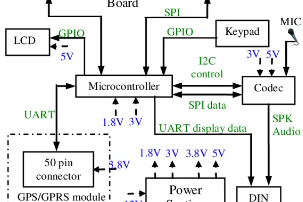
ステップ 8: ブロック図を描く
主要なモジュールを含むブロック図を作成する – プロセッサ, メモリユニット, 周辺機器, 外部インターフェイスとその他の主要なサブシステム. ブロック抽象化レベルで重要な接続とデータ フローを示す.
ステップ 9: 階層化された回路図の設計
場合によっては、 PCB スタックアップ 複数のモジュールが複雑になっている, 階層化された回路図構造の採用が最も効果的であることが判明. この階層図は、モジュール間の信号の流れを視覚的に示しています。. モジュールをクリックすると、その詳細が詳細に表示されます.
ステップ 10: コンポーネントリファレンス
この参照表には、標準的な電子コンポーネントと、回路図全体で使用される指定された参照インジケータがリストされています。. インジケーターは以下に準拠します IEEE 基準, 特定のコンポーネントの名前付けに大文字の使用を強調する.
| 成分 | 参照指定子 | 成分 | 参照指定子 |
| 抵抗器 | R | 電池 | BT |
| コンデンサ | C | ケーブル/ワイヤー | W |
| IC (集積回路) | U/IC | スイッチ | サウスウェールズ州 |
| ダイオード/LED | D | 基準 | FD |
| ヒューズ | NS | 発振器 | OSC |
| インダクタ/ビーズ | L | プラグ/コネクタ | P/CON |
| ツェナーダイオード | と | ヒートシンク | ひ |
参考文献- 回路基板のコンポーネント: 包括的なガイド
ステップ 11: シンボリック生成
回路図にはアクティブな要素などのさまざまな要素が含まれます。, 受け身, およびコネクタ, トランジスタなどの部品を組み込む, ダイオード, 論理ゲート, プロセッサIC, FPGA, およびオペアンプ. コンデンサなどの受動素子, インダクタ, 変圧器も付属しています. 標準ライブラリにない場合を除き、新しいコンポーネントを作成することは推奨されません。, シンボル作成に関しては IEEE 標準に準拠することが重要です.
ステップ 12: オペアンプ構成
シンボルを作成する際には IEEE 標準に準拠することが重要です, 特にオペアンプの場合. 描画プロセスの簡素化, 設計者は標準的な構成に従うことが多い, 入力ピンを左側、出力ピンを右側に配置, 電源ピンとグランドピンが垂直に配置されている. シンボルの方向や接続を変更する場合は、メーカーのデータシートとの整合性を確保することが重要です.
ステップ 13: 異種の回路図表記
PGAFのようなコンポーネント, メモリユニット, およびマイクロプロセッサ, 複数のピンが特徴 (データ, 入出力, 住所, コントロール, と電力線), 明確さを維持するために、単一パッケージ内の各サブコンポーネントを個別に表記する必要がある.
ステップ 14: ネットワーク接続
配線が電気接続を共有する交差点を適切にマークすることで、回路を明確に理解できます。. 回路図の簡略化には集積回路の表現が含まれます (IC) 過度にネットワークを描画する代わりに、一般的なシンボルを使用する. 名前が一致するデバイス間の整理されたピン間の接続を強調することで、可読性が向上します.
ステップ 15: 戦略的なコンポーネントの配置
回路図内の要素を慎重に配置すると、その後の部品表や IC パッケージの作成に大きな影響を与えます。.
ステップ 16: デザインルールのチェック
デザインルールチェックの活用 (コンゴ民主共和国) CAD 内で設計の論理的および物理的整合性を保証します, 計画中に有効な設計ルールへの準拠を評価する.
ステップ 17: ネットテーブルの検証
回路図設計の完了後, ネットリストの生成はレイアウトのインポートにとって重要です. このプロセスにより、機械可読なデータが生成されます。 (.MNL) 人間が判読できる (.TXT) 電気接続を表示するファイル. 設計エラーを防ぐために、ネットワークを手動で検証することをお勧めします。.
ステップ 18: 請求書 のf m材料
最新の CAD ツールには BOM 作成機能が備わっています, 設計者が部品の作成またはインポート中に必要なデータをすべて入力することが条件. BOM には製造部品番号などの重要な情報が含まれます (MPN), パッケージの詳細, サプライヤー名, またはサプライヤーの部品番号, 正確な文書化に不可欠.
ステップ 19: 回路図リスト
見落とされがちだが重要, 論理回路図リストは、過去の設計経験に基づいた重要な組織ツールとして機能します。. チェックリストにより図内のエラーを最小限に抑える, レイアウト設計者の作業を容易にする、エラーのない回路図を保証します。.
結論
このガイドでは、回路基板の回路図の作成について徹底的にまとめています。. 回路図を初めて始める場合でも、高度な知識を取得したい場合でも, この包括的なガイドは、高品質の製品を作成するための貴重な参考資料となることを目的としています。, コンセプトから完成までのすべての段階を通じた効果的なプリント基板の回路図. お願いします お問い合わせ 他にご質問がございましたら.