How to Choose the Right PCB Dielectric Material?


PCB dielectric material refers to the material that is non-conductive in nature, it is very important in the formation of the printed circuit boards. These materials act as insulators as well as barriers between the conducting layers to avoid direct connections and keep the signals clear. As the level of integration increased, the decision of the dielectric material used in printed circuit boards is crucial to reach satisfactory performance in critical applications. In this blog, we will discuss about 4 commonly used PCB dielectric materials and some advice on how to select the best one. Let’s get started with its definition.
What Are Dielectric Materials?
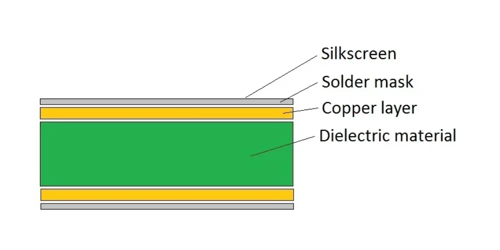
Dielectrics are materials that offer no conductivity and have the capacity to hold electrical charges and prevent their flow through the material. Two properties distinguish these materials: One is dielectric constant, which indicates how well the materials can store and transfer electrical energy. The other one is dissipation factor, which measures how poorly the materials are capable of storing electrical energy. A dielectric material in PCBs is used in between the conductive traces and places for electrical insulation so that no short circuit or signal interference occurs. The dielectric materials used in the board enable capacitance of the board and this is essential in high frequency ‘high speed’ circuits. Their values affect the electrical, thermal, and mechanical performance of the PCB including dielectric constant, thermal conductivity, and mechanical strength of the material.
Types of PCB Dielectric Materials


FR-4 (Flame Retardant 4)
FR-4 (Flame Retardant 4) is one of the most popular dielectric materials to manufacture circuit boards. It is an FC composite material that is made of reinforced glass fiber and epoxy resin binder. FR-4 has good electrical resistivity, mechanical properties, and fire resistance, therefore, it can be used in numerous applications. Nevertheless, its applications are somewhat restricted in high-frequency and high-speed systems because the dielectric constant of fr4 is comparatively high.
Further reading: A Comprehensive Guide to FR4 Thermal Conductivity
CEM-1, CEM-2 and CEM-3
CEM-1, CEM-2, and CEM-3 are ceramic-filled composite dielectric materials, widely used in high-frequency and high-speed PCBs. These materials have a lower dielectric constant and dissipation factor than FR-4 which makes signal losses and signal degradation lower. They also show great thermal coefficients, which help in the management of heat generated within the system. However, these materials are usually costly and require specialized manufacturing processes.
Polytetrafluoroethylene (PTFE)
Polytetrafluoroethylene (PTFE) is a fluoropolymer material that has electrical properties like dielectric constant and dissipation factor. Dielectric materials that are made of PTFE polymer are ideal for high-frequency circuits and microwave signal transmission, and circuits that are to be used in chemically aggressive environments and at high temperatures. However, they can cost more and can have very restrictive mechanical characteristics as compared to the other materials.
Polyimide
Polyimide is a PCB dielectric material that can be used in high operating temperature applications due to its thermal stability, low moisture pickup capability, and good dielectric value. This kind of material is commonly used in flexible and rigid-flex circuits and in circuits that need to be used at high temperatures or those exposed to aggressive chemical agents. However, they might be more pricey, and sometimes their processing is more complex.
Properties to Consider When Selecting PCB Dielectric Materials
When choosing dielectric materials for printed circuit boards, it’s essential to consider below 4 key properties:
-
Electrical Properties
- Dielectric Constant(DK)
This shows how much electrical energy the material can hold based on dielectric constant. This property influences the velocity of signals as well as the impedance; and low DK values are desirable in high speed applications.
- Dissipation Factor(DF)
The dissipation factor determines the dielectric losses, and figures characterized by lower DF values are suitable for high-frequency use. It affects signal attenuation and the amount of performance.
- Electrical Strength
Electrical strength refers to the intensity of electric stress that a material is capable of withstanding before it breaks down. This is very important for high voltage applications to ensure reliability and safety.
-
Thermal properties
- Glass Transition Temperature (Tg)
This is the temperature at which a polymer changes from being in a hard and glassy state to a soft and rubbery state. For mechanical applications especially those that operate at high temperatures, there is a tendency to use material with high Tg.
- Coefficient of Thermal Expansion (CTE)
CTE defines the extent of expansion or shrinkage of the material for changes in temperature. Another consideration is to try to make the CTE of dielectric materials used equal to that of copper in order to minimize mechanical stress and failure during continued use or thermal cycling.
- Thermal Conductivity
Thermal conductivity is a measure of how effectively a material can transfer heat flows from the high temperature region to the low-temperature region. Thus, increased thermal conductivity relieves the problem of efficient heat dissipation which is important especially with electronic circuits.
-
Chemical properties
- Moisture Absorption
Moisture absorption refers to the amount of water that a given material is capable of absorbing. Less moisture is preferred so as not to compromise the electrical properties and features like delamination.
- Chemical Resistance
This property measures the material’s ability to withstand effects of fluids or solvents, acids and other chemicals. It is an important parameter to measure whether a PCB can be used in harsh environments.
Conclusion
The choice of the dielectric material in the printed circuit board is a very important factor. It could greatly affect the performance of the board, its reliability and applicability for the intended purpose. As mentioned in this blog, each dielectric material has different characteristics including electrical, thermal, mechanical, and chemical. Still unsure which material will be perfect for your project? Contact us now. Our engineers are always available to assist you and give you the best advice to choose the right PCB board dielectric material.
Recent Posts
Impedance Matching: A Critical Factor in High-Speed PCB Design
Impedance matching has become a cornerstone of the signal integrity in the realm of high speed PCB…
How to Clean a Circuit Board Safely and Effectively?
It is important to learn how to clean a circuit board properly if you’re working…
Counterbore vs Countersink: Which to Choose for Your PCB?
When designing PCBs, selecting the appropriate type of holes for fasteners is crucial. And much…
PCB Copper Foil: Types, Properties & How to Choose
PCB copper foil is one of the most critical materials in the printed circuit board…
MOKO Technology Launches Vietnam Manufacturing Base in February 2025
Shenzhen, China - February 11, 2025 - MOKO Technology, a leading global electronics manufacturing service…
PCB Solder Mask: What It Is and Why Every Circuit Board Needs It?
While most people focus on the components and copper traces that make up PCBs, there's…


