How can I remove tenting on vias after assembly for debugging?

I have two BGA parts on a PCB, with a 32 bit wide bus with a few control lines and a clock line connecting them. Almost all of these traces are only on internal layers. There looks like a signal integrity problem on the bus. The good news is that the board only has parts on one side, and all the vias are through-all. Can anyone suggest good ways to remove the tenting over the vias so they could be probed with an oscilloscope, or at least be able to solder 30 gauge wire to them?
  • Use a fiberglass brush pencil.
  • Or try a small brass wire brush before practicing on a scrap board first. It would be best to get control of the brush by chucking it in a drill press (or mill if you have one) and use a heavy solid block of material (a cast iron angle bracket if you have one) and double-face tape the board to the angle bracket.
  • Certain more aggressive flux removerswill, with sufficient time and agitation, also remove the solder mask. If very thin traces are involved, this might be safer than using a fiberglass or brass brush.

Read More: BGA PCB Assembly

#PCB Assembly

Picture of Oliver Smith

Oliver Smith

Oliver is an experienced electronics engineer skilled in PCB design, analog circuits, embedded systems, and prototyping. His deep knowledge spans schematic capture, firmware coding, simulation, layout, testing, and troubleshooting. Oliver excels at taking projects from concept to mass production using his electrical design talents and mechanical aptitude.

What Others Are Asking

Are SMT components bad for high voltage applications?

Many assembly factories are asking for SMT jobs, while I think through hole would be a better option for a high voltage application. Before the high voltage project is started, we need to make a call on SMT or Through hole parts. Is there a study on this?

What are the black spots in lead-free solder joints on PCB?

I am prototyping a PCB, using Chip Quik’s “SMDSWLF.031, a Sn96.5/ Ag3.0/ Cu0.5 solder with 2.2% no-clean flux. I find that the black spots appears frequently in larger pads on my board. I wonder if it is because I left the soldering iron more time heating the solder and that burnt the flux. What is that black residue? Is that a sign of a bad joint or maybe bad soldering technique?

Read Detailed Advice From Blog Articles

Introduction to SMT PCB Assembly
Will Li

Introduction to SMT PCB Assembly

SMT PCB assembly has become the most popular PCB assembly technology since the 1980s, and is now widely used in industries such as consumer electronics,

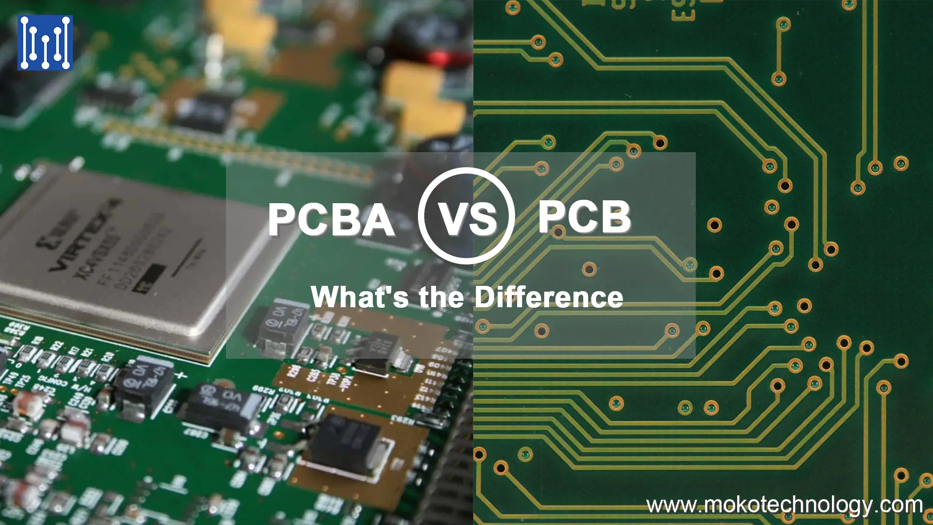
PCB vs PCBA: What’s the Difference
Will Li

PCB vs PCBA: What’s the Difference?

PCB and PCBA are the two most common terms in the electronics industry. Although the difference between them is only one letter, they represent different

Scroll to Top