Los dispositivos electrónicos que utilizamos cambian y se actualizan constantemente.. Cada vez son más pequeños y funcionales, lo que hace que el diseño electrónico sea más desafiante. Porque en este caso, electrical interference is becoming more and more sensitive. To ensure the stability of these devices, a vital component is the decoupling capacitor. These compact yet highly efficient components are crucial in ensuring that our circuits run smoothly and reliably. So how do these components work? Let’s read this article to find out and understand why they are indispensable in modern electronics.
What Are Decoupling Capacitors?
Decoupling capacitors are passive electronic components that will store energy temporarily locally in a circuit. The primary purpose is to provide a stable voltage supply source to the integrated circuits and other sensitive components by suppressing high-frequency noise and compensating for rapid changes in current demand. You can imagine a decoupling capacitor as a small power supply that is situated near the IC. In the case the current required by the IC shifts suddenly to a higher value than what is supplied by the power supply, the decoupling capacitor provides for the burst. Por otra parte, during the times that there is high voltage or noise on the power rail, the capacitor takes this energy and isolates any noise from reaching the IC.
Coupling Capacitor and Bypass Capacitor: Cual es la diferencia?
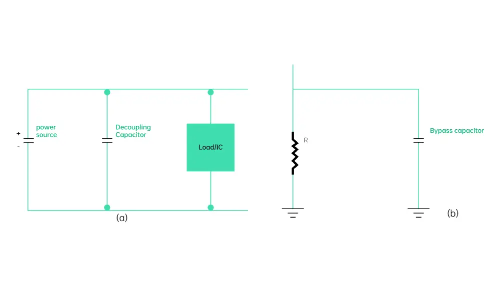
A bypass capacitor decreases the chances of noise frequencies penetrating the system since it bypasses them to the ground. It is placed between the supply voltage (vcc) and ground (GND) pins to help reduce noise and voltage spikes in the power supply lines. The bypass capacitor provides the route for the return path of the AC signal between the grounded and powering rails. While decoupling capacitors store energy and discharge it back into the power rail to ensure a steady current flow.
As their role and operation are concerned, it can be noted that bypass and decoupling capacitors are actually quite similar. In powering any unit, the main goal is to create a constant low impedance node concerning the input power ground. Some of the few noticeable differences are: Bypass capacitors are just as their name implies; they offer a low impedance route for the HF noise signals to follow. It adopts techniques that prevent high-frequency noise before it is allowed to circulate in the whole circuit leading to circuit failure and an EMI issue. While for decoupling capacitors, they are used to regulate voltage fluctuations and disturbances.
For low-impedance shunting, only one electrolytic capacitor is needed while for stabilizing the signal two capacitors of two different types must be used.
How Do Decoupling Capacitors Work?
Decoupling capacitors work on two main principles:
Charge Storage: They store electrical charge and can quickly release it when needed, providing a local source of current for ICs during sudden demand spikes.
Low-Impedance Path: En altas frecuencias, capacitors act as a short circuit between power and ground, effectively shunting high-frequency noise away from sensitive components.
When an IC demands an additional current, the decoupling capacitor near to it can supply this instantaneously, much more quickly than the power supply can. This is useful in maintaining the voltage level at the IC so as to minimize the voltage fluctuations that might disrupt the circuit.
Types of Decoupling Capacitors
Existen 4 different types of decoupling capacitors that are used for various purposes within a circuit:
Ceramic Capacitors: These are the most common type used for high-frequency decoupling. They’re small, have low ESR (Equivalent Series Resistance), and work well for frequencies above 1 megahercio. Common values range from 0.1 μF to 0.01 μF.
Electrolytic Capacitors: Larger electrolytic capacitors (1 a 100 μF) are used for low-frequency decoupling and bulk energy storage. They’re placed further from the ICs but still play a crucial role in maintaining overall power stability.
Film capacitors: These capacitors are used for high and low frequency decoupling uses and they are available in varied capacitance values and voltage ratings. They exhibit terrific insulation characteristics and stability over a very wide range of temperatures and frequencies.
Tantalum Capacitors: Tantalum capacitors have a very high capacitance rating and low ESR, which makes them ideal for low frequency decoupling purpose. They have a high capacitance density, and they also have a high volumetric efficiency, making them a go-to choice for deployment in small electronic devices.
Best Practices for Using Decoupling Capacitors in PCB
To get the most out of decoupling capacitors, consider these best practices:
- Place decoupling capacitors closeto the power pins of ICs they’re intended to decouple. This proximity minimizes loop area and reduces inductance, enhancing the capacitor’s effectiveness at filtering high-frequency noise.
- Use short, direct connections to both power and ground. For power planes accessed via vias, connect the capacitor to the componentpin first, then to the via to ensure current flows through the plane effectively.
- For input and output signals, place capacitors in-line with the trace to filter low-frequency transients while allowing high-frequency signals to pass.
- Maintain continuous and adjacent power and ground planes. Distribute capacitors across the area they’re decoupling when possible. For capacitor banks, alternate orientations to prevent effective splits in ground or power planes.
- The number of capacitors should correspond to the power and ground pins in the area and the number of I/O signals. Provide at least one decoupling capacitor for each power pin on an IC.
- In designs with both analog and digital sections, implement separate decoupling schemes to isolate noise between these domains.
- Ensure power and ground planes are symmetrically placed in the design. Minimize the layers between planes and decoupling capacitors for optimal performance.
- Choose the right capacitor type. For high-speed digital circuits, ceramic capacitors with low ESR and ESL (Equivalent Series Inductance) are usually the best choice. For analog circuits or lower-frequency applications, other types may be more suitable.
Conclusión
Although decoupling capacitors are usually small and cheap, their contribution to the overall design of the circuit is huge. They keep our electronic devices functioning smoothly, suppressing noise and providing stability in an increasingly noisy electronic world. We hope that by understanding these theories and how to apply them appropriately, engineers can design goods that perform optimally in varying circumstances. No matter whether the circuit in question is a tiny microcontroller circuit or an intricate high-speed application, careful consideration of decoupling requirements will be well rewarded in terms of the final product’s dependability and productivity. The next time you’re laying out a PCB, remember that these little components could be the game changer for your design.