Heutzutage, electronic products are both compact and lightweight while performing a variety of functions. This is largely due to effective PCB thermal management. On the printed circuit boards, various components are assembled to achieve different functions, während des Prozesses, they would generate heat more or less, especially when packed in a small space. If the heat becomes excessive, it could impact the PCB performance, or can even cause device failure. Daher, PCB thermal management improvement is required in the PCB design process.
What Is PCB Thermal Management?
Thermal management of PCB is the methodology that controls the heat produced by components placed on the PCB. To improve PCB thermal management effectively, we can find many solutions and techniques, such as the use of Temperatur fällt, thermische Durchkontaktierungen, copper planes, usw. to distribute as well as remove the heat efficiently from the specific areas of the PCB. What we are trying to achieve is to always keep all the components operating optimally, so as to lengthen the life and improve the performance of the electronic device.
7 Commonly Used PCB Thermal Management Techniques
To effectively manage heat in PCBs, designers employ a variety of pcb heat dissipation techniques. Here are seven of the most commonly used ones:
-
Use of Appropriate Materials
When designing PCBs, we should pay close attention to the choice PCB Materialien for better heat management. Zum Beispiel, using thermal conductivity materials like copper can dissipating heat from power-hungry components easily. zusätzlich, thermal expansion coefficients of the materials is also to be considered. We can choose materials with a similar coefficient of thermal expansion as those components to help us minimize stress, and the eventually prevent failures due to temperature fluctuations. Zusätzlich, the use of materials with lower Dielektrizitätskonstante can serve to reduce likelihood of hot spot formation on the board, and increase heat dissipation.
-
Strategic Component Placement
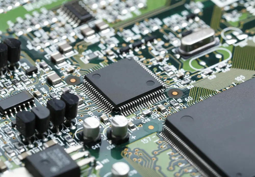
Effective thermal management relies on thoughtful component placement. Heat-generating components should be positioned near cooling devices such as fans or heat sinks, ebenfalls, they should be put in well-ventilated areas. It’s advisable to keep at least 2cm of distance between high power components to let them dissipate heat properly. The spacing also prevents localized heat buildup, and helps the board to remain evenly at temperature.
-
ImplementingThermal Via Arrays
Using thermal via arrays can also improve heat conduction in PCBs . These arrays come in two main varieties: simple vias and filled and capped vias. Simple vias are popular for their thermal resistance reduction capability, however filled and capped vias often outperform in heat dissipation since they can be placed directly under thermal pads to extract the heat in a more efficient way.
-
Sufficient Trace Width & Dicke
A PCB’s thermal performance is very much dependent upon the copper trace width und Dicke. Provision of low impedance paths for current flow requires adequate dimensions. In high current areas, this is especially important since an insufficient trace dimensions could cause an increase in power loss and heat generation. And therefore it is important that trace width and thickness be thoroughly considered to minimize heat issues.
-
UtilizingHeat Sinks
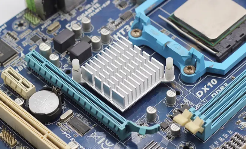
Conduction based heat sinks are effective in cooling devices, where high temperature area is transferred to the low temperature area by conduction. To achieve that, they remove heat from PCB components and release it through fins with a larger surface area. In selecting a heat sink, designers should examine material thermal resistivity, fin design, mounting technique and thermal interface material used.
-
Using Heat Pipes
In compact designs with limited space, heat pipes are a suitable passive heat transfer solution. They offer reliable cooling with vibration free and quiet operation, good thermal conductivity and low maintenance requirements. The pipe usually contains small amount of Nitrogen, Wasser, acetone or Ammonia. They absorb the heat, transporting the vapor along some pipe. As the vapor passes through, the pipe has a condenser and that vapor becomes liquid again and the cycle continues.
-
Implementing Cooling Fans
Another popular PCB thermal management technique is the use of cooling fans that blow hot air out of the area to prevent overheating. This technique is well known for high-current applications, such as power supplies, as these fans offer convenient and, most importantly, rapid heat removal, allowing components to perform efficiently and last longer.
How to Identify PCB Thermal Issues?
Even with careful design, thermal issues can sometimes arise. You need to know how to identify these problems. Here are some methods to detect thermal issues:
- PCB Thermal Analysis Tool
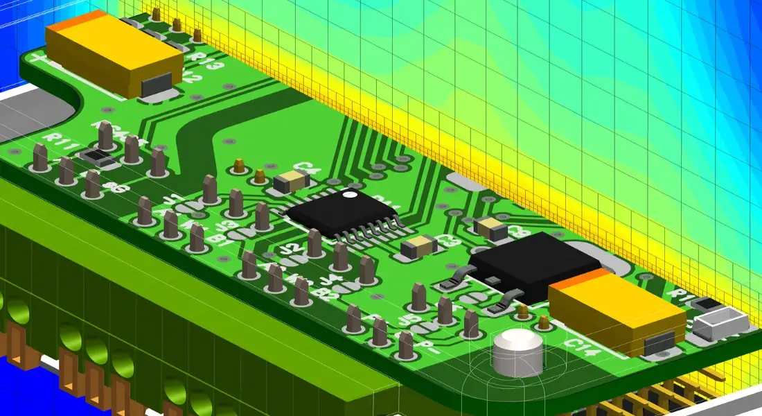
Thermal modeling is a key part of the thermal analysis in PCB design for failure analysis. It also gives designers insight into thermal issues inherent to their circuit, and will help them in selecting proper cooling methods and PCB design techniques. PCB designers can use suitable modeling software to determine which is the best layout or the best position of the components in the layout. Thermal modeling allows designers to quickly and easily understand heat flow patterns, design heat sinks, and create cooling for active devices.
- Visually Inspect the Board
Visual inspection is another approach to finding overheating, burnt or partly damaged components, dry joints, and arcing. Bulging or burnt components and discolored spots on the PCB are all visible indicators. Beyond visual cues, unusual odors from the board can also indicate heating issues. This simple technique allows for quick identification of thermal problems without powering up the board.
- Use Infrared Cameras
IR cameras allow painless evaluation of powered prototype boards for heat culprits and unknown issues you can’t see with your naked eye. But these cameras also show at which parts of the heat is then generated and also aid in distinguishing between counterfeit or defective parts based on their thermal signature compared with original components. Zusätzlich, the thermal imaging cameras are capable of spotting PCB tracks that have insufficient solder, which leads to higher resistance and increased heat dissipation.
Letzte Worte
Effective PCB thermal management is required to achieve the reliability and performance of electronic devices. Thermal issues becomes the primary aspect to be considered in the beginning of the design process. By using the techniques mentioned above, we can effectively manage the heat of the board. As electronic products progress to smaller and more compact designs, with increasingly greater numbers of functions, it is certain that these will present greater challenges to PCB thermal management. Deshalb, for PCB designers, learning PCB thermal management techniques is a necessary skill.
