Although BGA is a well-known package, many people still not have a understanding of its differences towards LGA. This text will make a detailed comparison between This text will make a detailed comparison between BGA vs LGA, and help you make a purchase decision between them.
What is BGA
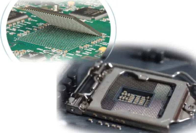
Ball grid array is a surface attachment package technology for fixation of microprocessor to integrated circuit. Coming with a bottom full of balls, it offers more leads than DIP and QPF for connection.
BGA: Advantages and Disadvantages
High Density
BGA is a solution born in the situation where large amount of pins should be organized in a limited space. It allows high density of pins but low risk at solder bridge.
Thermal Conductivity
Between balls of BGA and board, there is low thermal conductivity, so the heat produced by integrated inside the package can be delivered to the board with ease to avoid IC overheating.
Low Inductance of Balls
Compared to common pins, balls are so short in shape that unnecessary inductance decreases. In high speed PCB, it also helpfully prevents signal distortion.
Non-ductility of Balls
However, shape like a ball leads to another problem, non-ductility. If there is any desynchronized bend between balls and board due to different coefficient of thermal expansions, or any mechanical stress applied on the device, the solder point is likely to be broken.
We can solve the former by using a material with similar thermal properties as PCB. For example, plastic BGA is highly recommended to PCB production rather than ceramic type. It is also advisable to use lead-free solder product line to reduce damage during manufacture. Lead-free solder, which conforms to RoHS, performs reliably under high temperatures, high thermal shock and high G-force. Otherwise, when the PCB goes through reflow solder, problems like head in pillow and pad cratering may occur.
For the latter problem, mechanical stress, it is highly recommended to conduct an under-filling process. Simply speaking, we should inject an epoxy compound between the board and the device, after the whole device attach to the PCB. The second way to handle mechanical stress is inserting ductile coating into the BGA package as a buffer, so the tin balls are allowed to self-adjust following to the movement of packages. Last but not least, adding inter-posers between BGA package and PCB is not a bad solution.
Inconvenient Testing
When BGA packages have been soldered, it is not so easy to inspect solder problem covered by the component body. In order to make sure high-quality soldering of BGA packages bottom, factory usually adopt X-ray machine and CT scanner. If the BGA package have a bad soldering, rework station is a helpful machine to remove it. It is equipped with infrared ray or warm air device, thermocouple, and vacuum facility so as to grip the package with bad soldering. Then, we can reball the package and reinstall it on the board.
Since the high-cost of X-ray inspection machine, some people, instead, adopt circuit testing way, such as boundary scan test method conducted through IEEE 1149.1 JTAG port.
Uneasy Temporary Connection For PCB Trial
In the beginning of PCB development, we need temporarily connection between package and circuit in order to debug the performance of the whole PCB. In the case, shape of ball is too uneasy to attach on the circuit, even though we just need it for temporary trial. Fortunately, socket like ZIF and elastomer socket can solve this problems very well. They can realize both balls stable connection and easy removement after trial without any effect on further formal soldering.
What is LGA
When it comes to LGA, sockets is not a temporary accessory for trial period but a fixation frame used in long run. There are lots of tiny contacts on the underside of LGA. They are used to connect to the contacts on the PCB side. With the fixation of the socket, electrical linking is well built up between the package and the board. And, if you want to replace the IC, just feel free to loosen the socket and put it out.
In addition to socket, electrical connection between PCB and LGA can be set by traditional soldering, too. However, any removement of package is not allowed after finishing electrical connection.
LGA: Advantages and Disadvantage
Good Electrical Connection
It offers stable electrical linking and mechanical stability, avoiding the problem of pin skewing, short-cut and open-circuit.
Convenience Maintenance
We don’t need to desolder the package if it doesn’t work, since socket fixation can be undone just by pressing the lever. Then, the bad package is put out. Similarly, new IC can be installed with ease just by pressing the lever on the socket.
Two Connection Ways
LGA can be connected to the PCB not only by proper socket but also by common soldering. This offer more choices to fit the PCB layout.
Risky Soldering Process
However, if you choose to connect LGA by soldering, the process will be risky. Due to the low height of its pins, empty holes and tin beads may occur after soldering. These unexpected situation will lead to low-quality connection to the board.
Flexibility For PCB Layout
It frees the PCB layout between IC port and motherboard. The pins of LGA does not go through the board, so signal layer is available for more circuit layout. There will be less limitation for the organizations of other components. In this way, it contributes to the flexibility of PCB design.
Consideration About Choosing BGA Vs. LGA for PCB
LGA Package Vs BGA Reliability
The pins of LGA packages provide stronger mechanical holding than BGA’s.
Proper Connection Way for Your PCB Design
Think about whether you want balls soldering connection or pin connection with socket. If you want good signal transmission but do not care about further replacement, choose BGA package.
Pin Quantities You Need
The pin density of BGA is higher than LGA’s. If you are handling complicated PCB design, choose BGA package.
Heat Dissipation of BGA Vs. LGA
Since the contact area of ball is bigger than pins, the heat dissipation of BGA is better than LGA’s. If your IC emits heat seriously during operation, choose BGA package.
Maintenance Requirement
If you need to change IC, choose LGA with sockets. It is more easier and cost-saving than using BGA.
Recommended Application of LGA Vs BGA Package
BGA is widely used in the field of smart phone, tiny laptop and portable tiny device, while LGA is commonly applied in CPU board and camera module.