Are the two modules interfering with each other in a PCB with GSM module and the gp-635t GPS?

In my current prototype, I have a SIMCOM GSM module and the gp-635t GPS. They are both in an enclsoure including antennas (gps antenna is integrated). What I experience is sometimes poor GSM and GPS connectivity and sometimes GPS doesn't get any fix (in the 2 minutes of time i allocate for it) and the GSM fails to send data sometimes. Any tips on this case?

No. Antenna signals shouldn’t interfere since the GSM and GPS are on different bands.  However, the electronics might interfere with each other.

Put GPS and GSM modules on their own ground planes such that all the parts are covered, then connect ground and supply in one place, plus bypass it with capacitors right there. Use at least three – some high-quality 22pF in small package (0402), 1nF, and 100nF. At least the first two should be with NP0 dielectric. It is also a good idea to bring the power from the other layer and to connect the two grounds (for GSM and GPS planes respectively) as close as possible to the input power connector (or battery).

Read More: IoT Electronics Manufacturing

#PCB Design
Picture of Oliver Smith

Oliver Smith

Oliver is an experienced electronics engineer skilled in PCB design, analog circuits, embedded systems, and prototyping. His deep knowledge spans schematic capture, firmware coding, simulation, layout, testing, and troubleshooting. Oliver excels at taking projects from concept to mass production using his electrical design talents and mechanical aptitude.

What Others Are Asking

What type of PCB material should I use?

I’m making my first 4 layer PCB (1 signal, 2 GND plane, 3 PWR plane, 4 signal) with impedance control. How do you know what type of material to use? Is FR4 material ok for the 50 Ω and 90 Ω impedance?

Read Detailed Advice From Blog Articles

PCB Shield: Types, Benefits, and Layout Tips
Ryan Chan

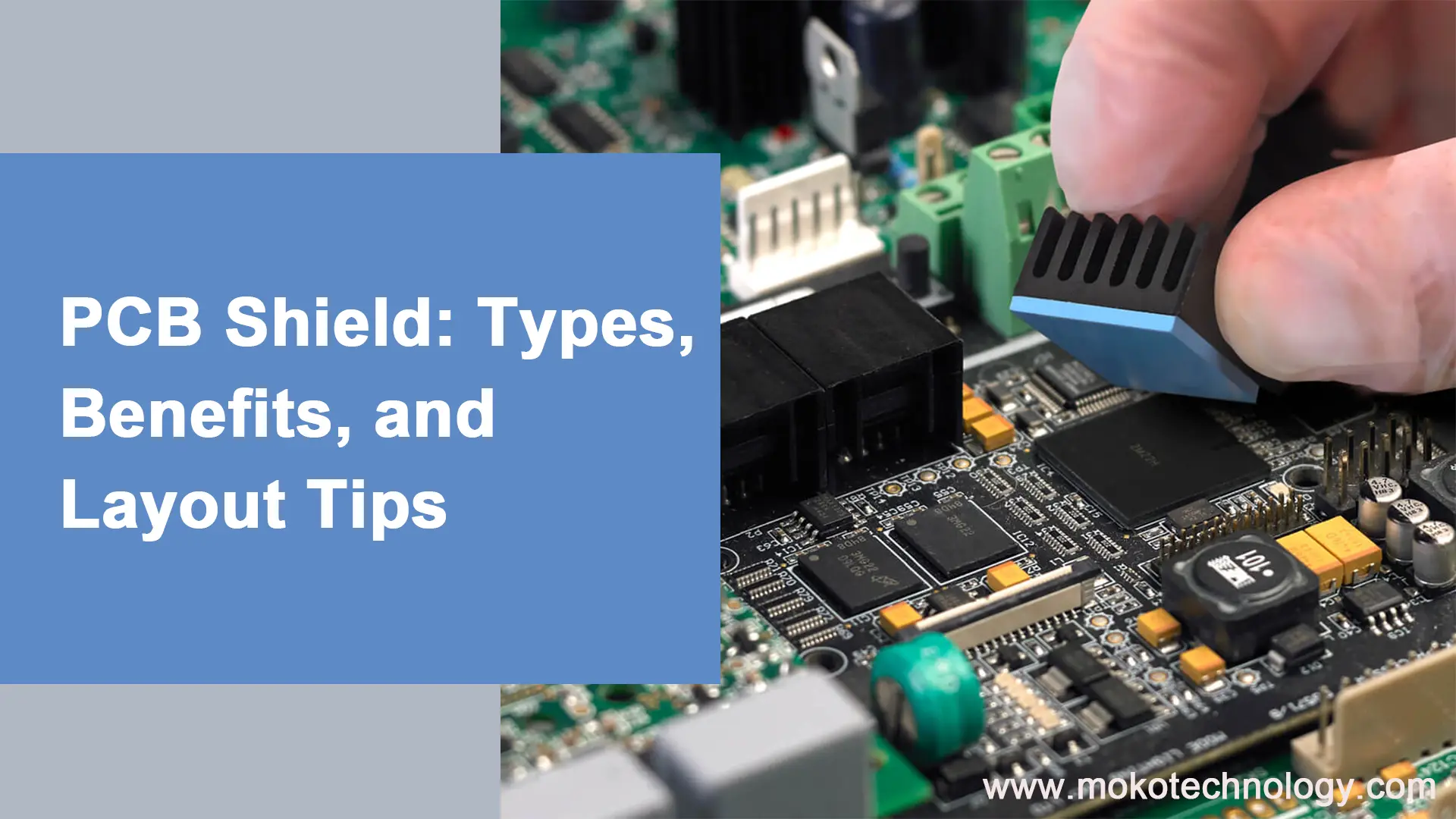
PCB Shield: Types, Benefits, and Layout Tips

Printed circuit board (PCB) designers often grapple with electromagnetic interference when laying out boards. They must consider electromagnetic compatibility to satisfy system specs. Even small

How to Achieve Target PCB Impedance Control
Ryan Chan

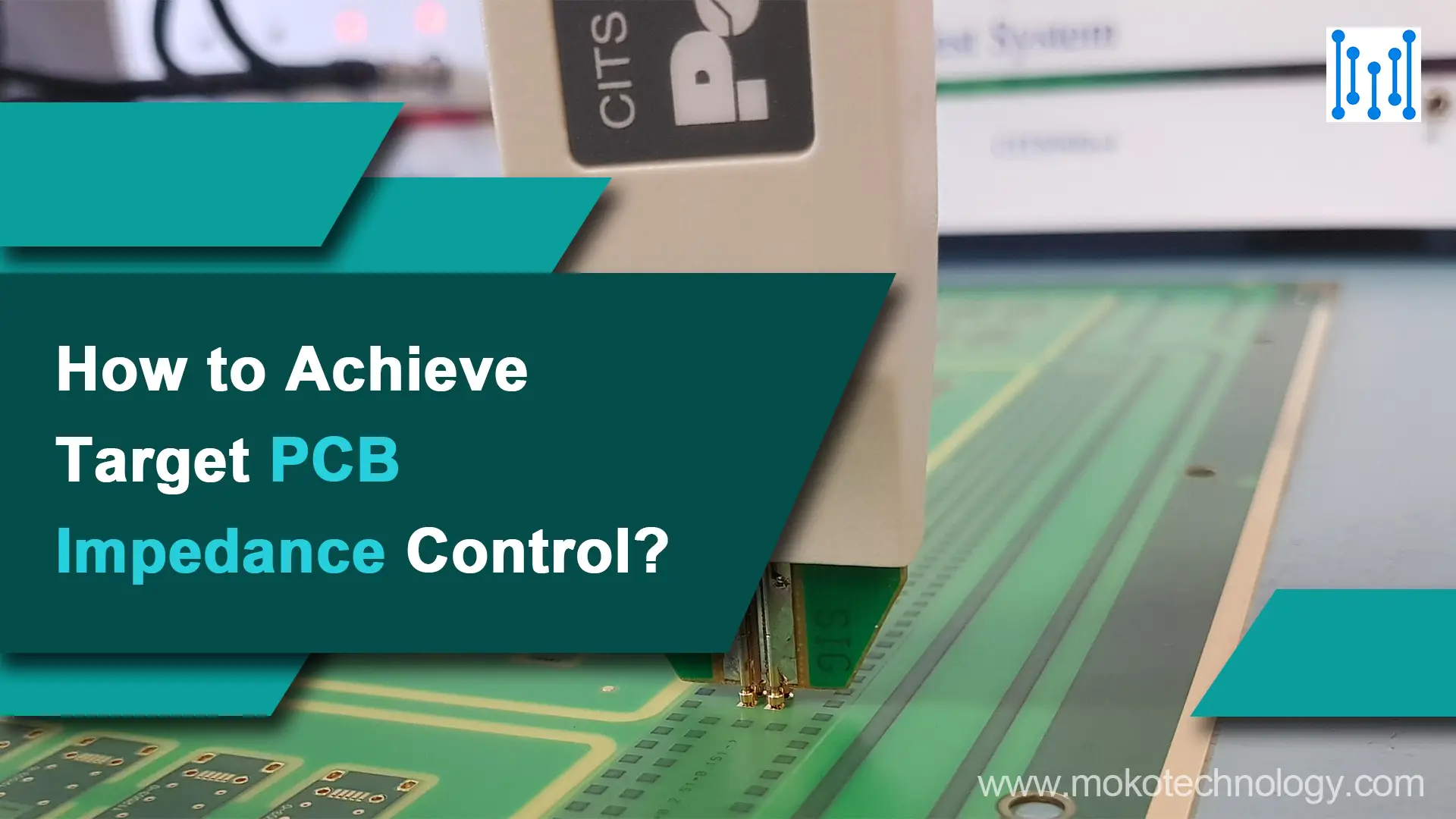
How to Achieve Target PCB Impedance Control?

As printed circuit boards become smaller and faster, controlling impedance is crucial for managing signal integrity. With circuits operating in the GHz range, even signals

Scroll to Top