A Comprehensive Guide to PCB Prepreg


Prepreg, short for pre-impregnated composite fibers, is an essential material in the manufacture of multilayer printed circuit boards. However, it is often overlooked compared to more visible PCB components like copper traces and solder mask. This article will lift the veil on this vital part of multilayer board construction. We’ll explore what prepreg is, how it’s made, key material properties, common types, thickness considerations, and more. Read on to gain a better understanding of PCB prepreg!
What Is Prepreg in PCBs?
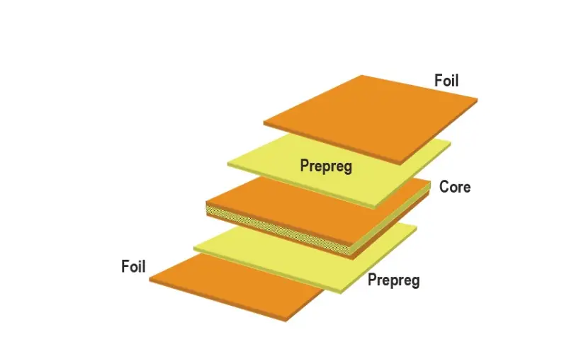
Prepreg consists of thin fiberglass cloth that has been pre-impregnated with a specially formulated epoxy resin system. The resin is partially cured to form a tacky, solid sheet material called a B-stage prepreg. This allows the resin to flow and bond when laminated, without being fully cured and solid. Prepreg sheets are stacked up alternating with copper foil layers. The multilayer layup is laminated under heat and pressure, causing the prepreg resin to flow and bond the layers into a solid laminated board. The prepreg provides excellent dielectric properties and adhesion between circuit layers. And because prepreg has a precise thickness, it enables PCBs with tightly controlled dielectric layer distances.


How Are Prepregs Made?
- Selecting and preparing the reinforcement material: The reinforcement is typically a woven glass fiber mat or cloth. It needs to be cleaned and prepared to ensure proper adhesion and impregnation with resin.
- Mixing the resin system: The resin system typically consists of an epoxy resin, curing agents, catalysts, flame retardants, and other additives. These components are measured out and mixed thoroughly.
- Impregnating the reinforcement: The resin mixture is used to impregnate the woven glass reinforcement, typically by dipping the fabric into the resin or using a process like hot melt coating. This allows the resin to fully penetrate the weave.
- Partial curing: The impregnated material then goes through a partial curing step, often using heat. This b-stages the resin, meaning it is not fully cured but is in a tacky, solid state.
- Treating: The prepreg may undergo additional treatments such as pressing to achieve consistent thickness or adding protective films.
- Packaging: The prepreg is typically layered between release films or papers, and may be cut into sheets or rolls. This protects the material and makes it easier to handle.
- Storage: Prepregs are stored frozen or refrigerated to prevent additional curing before use in PCB fabrication. This maintains their shelf life.
- Use: When ready for PCB fabrication, the prepreg layers are thawed, laminated with copper foils, and fully cured under heat and pressure.
Properties of PCB Prepreg Materials
Prepreg materials have several properties that determine their performance and applicability:
Resin System – The epoxy formulation controls key characteristics like resin Tg, dielectric constant/loss, thermal stability, moisture absorption, and Z-axis CTE. Popular systems include FR-4, high-Tg, and halogen-free.
Fiberglass Weave – Standard 106 and 7628 glass styles provide the best balance of properties. Tighter weaves enhance punching performance but reduce resin loading.
Resin Content – Typically in the 45-55% range. Higher resin content gives better filling but increases dielectric constant. Lower resin content aids punching.
Filler particle size and loading – Fillers like silica reduce the CTE but increase dielectric constant and loss. Larger particles enhance laminating flow while smaller ones reduce filler fallout.
Drape and Tack – Controllable properties that determine prepreg handling and layer-to-layer registration.
Flow/Fill – The melt viscosity during lamination impacts filling performance, especially in fine features.
Types of PCB Prepreg
-
FR4 Prepreg
FR-4 is the standard, general-purpose prepreg material used for the majority of PCB manufacturing. It employs a brominated epoxy resin reinforced with woven fiberglass that offers a good balance of processing ease, dimensional stability, thermal performance, dielectric properties, and cost. FR-4 prepreg has a typical glass transition temperature in the range of 130-140°C.
-
High Tg Prepreg
High Tg prepreg uses specialized epoxy resin systems to achieve glass transition temperatures of 170°C or greater, meeting the demands of high-reliability PCBs used in aerospace, defense, and other extreme environments. The highly thermally stable resins withstand soldering, annealing, and other processes up to 230-290°C. High Tg prepregs provide enhanced thermal and mechanical performance but at a higher cost than standard FR-4.
-
Halogen-free Prepreg
Halogen-free prepregs utilize resin systems that do not contain bromine or other halogens that can generate hazardous byproducts when burned. Popular halogen-free resin systems include bismaleimide triazine (BT) epoxy, cyanate ester, and modified epoxy. Halogen-free prepregs provide environmental benefits but also higher cost and more complex processing compared to standard FR-4.
-
High-Speed Prepreg
High-speed prepreg uses engineered resin systems to achieve stable dielectric properties and low dielectric loss for reliable high-frequency performance. Common resin systems include polyphenylene ether (PPE) blends and fluoropolymers that obtain dielectric constants under 3.5. High-speed prepreg enables PCB designs for RF, microwave, high data rate, and other demanding applications.
How to Choose the Right PCB Prepreg Material?
With so many prepreg options, it’s vital to match the material properties to the application requirements:
Signal Integrity – Low Dk and Df prepregs will enable higher speed signals with reduced loss and dispersion. Ensure impedance tolerance is within specifications.
Thermal Management – If high thermal stability is needed, choose a prepreg with a high Tg resin system. This allows lead-free assembly and reliability under temperature cycling.
Environment – Halogen-free prepregs prevent emissions of dangerous substances like dioxins when burned but cost more than standard FR-4.
Stackup – Thinner prepreg allows tighter vertical traces and vias. Standard 106 glass works well while tighter 7628 weaves can help with very fine geometries.
CTE – Adding more layers stresses plated through holes, so lower CTE prepreg helps prevent barrel cracking. This balances against an increased dielectric constant.
Cost – While other prepregs provide the ultimate in performance, standard FR-4 will be completely adequate for many applications at a lower cost.
PCB Prepreg Thickness and Its Impact
Prepreg thicknesses typically range from 0.002 inches (2 mils) up to 0.025 inches (25 mils). The trend has been towards thinner materials to enable finer lines and spaces, smaller vias, and tighter impedance control. Some key impacts of prepreg thickness:
Thinner dielectrics allow tighter routing geometries. 0.002” prepreg enables 2/2 line/space versus 4/4 with 0.004” material.
Thinner dielectrics reduce signal loss, but microvia reliability may become problematic below 0.003”.
Standard 0.014”-0.020” prepregs work well for broad impedance control and high voltage isolation.
Thicker prepregs above 0.020” provide greater breakdown voltage through wider gaps. Allows sparing use of costlier intermediate layers.
In summary, prepreg thickness exerts tradeoffs between cost, design geometries, and electrical performance. As always, choose the prepreg thickness appropriate for each specific application rather than arbitrarily.
Conclusion
Prepreg materials are a complex but critical part of the PCB design and manufacturing process. As we’ve explored, factors like resin type, fiberglass style, flame retardants, and more all contribute to prepreg’s electrical, mechanical, and thermal properties. While it may seem like an opaque black material, intelligent prepreg selection enables engineers to dial in PCB stackups for optimal performance.
The variety of available prepreg types is vast, so collaborating with experienced manufacturing partners is invaluable. MOKO Technology has the expertise to guide customers in choosing the right prepreg to optimize stackups. Contact us today to tap into more prepreg knowledge.
Recent Posts
Impedance Matching: A Critical Factor in High-Speed PCB Design
Impedance matching has become a cornerstone of the signal integrity in the realm of high speed PCB…
How to Clean a Circuit Board Safely and Effectively?
It is important to learn how to clean a circuit board properly if you’re working…
Counterbore vs Countersink: Which to Choose for Your PCB?
When designing PCBs, selecting the appropriate type of holes for fasteners is crucial. And much…
PCB Copper Foil: Types, Properties & How to Choose
PCB copper foil is one of the most critical materials in the printed circuit board…
MOKO Technology Launches Vietnam Manufacturing Base in February 2025
Shenzhen, China - February 11, 2025 - MOKO Technology, a leading global electronics manufacturing service…
PCB Solder Mask: What It Is and Why Every Circuit Board Needs It?
While most people focus on the components and copper traces that make up PCBs, there's…


