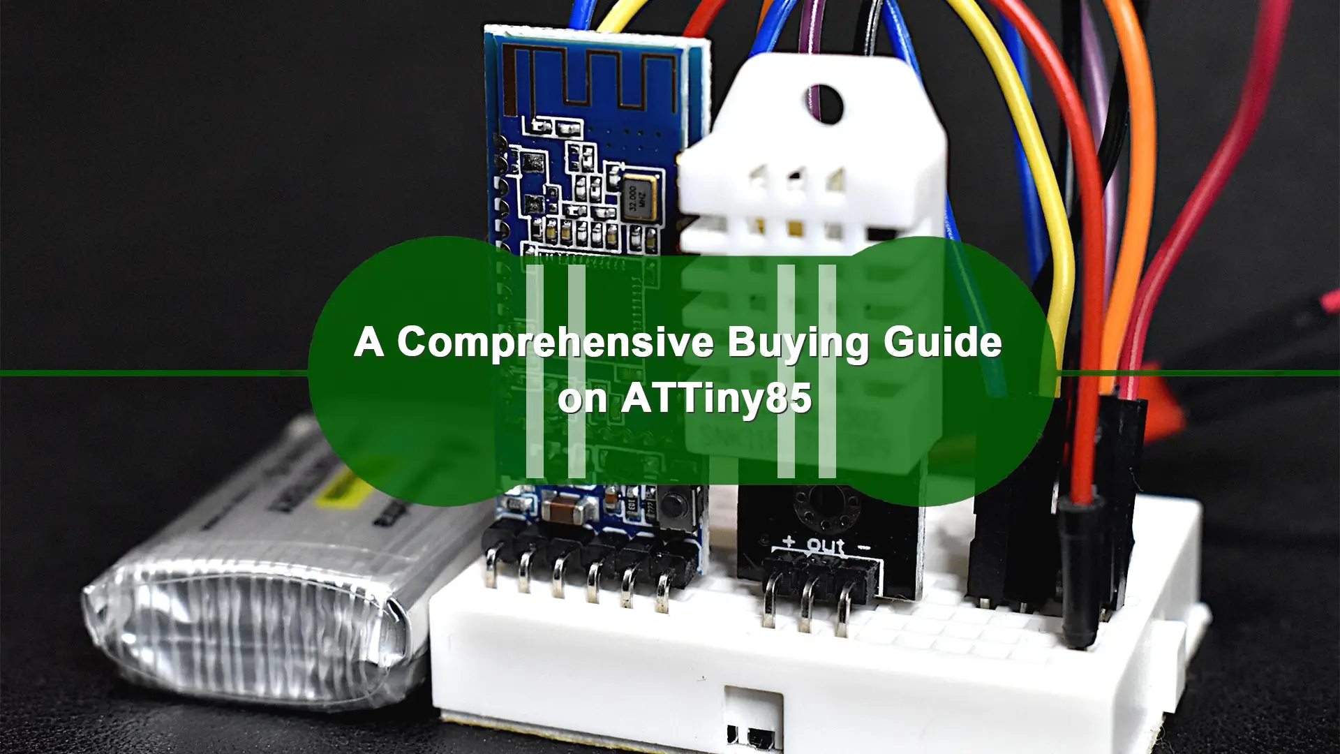
This text will clear all your confusion during any process of ATTiny85 purchase, containing its specification, pin configuration, distinguish against other Attiny chips, details about Attiny85 family, purchase consideration, and some tips on how to use it when you get it.
What Is the ATtiny85 | Before Buying
The ATtiny85 is a small, high-performance micro-controller based on AVR. It is equipped with a RISC CPU. It comes in two package forms which fit different interfaces and control of sensors and devices. Satisfyingly, it can realize low power consumption with an MSSP and a 10-bit ADC. RAM-512 bytes and EEROM-8kb of ATTiny85 offer saving space for instruction code. There are also timers, SPI communication, 12C communication, BOD (Undervoltage reset), interrupts, and ADC in the little main body of ATTiny85. Various storage is available, such as FLASH, EEPROM, and SRAM. This makes it an absolutely versatile and useful device.
Specification
Now it is time to show more about its specifications and parameters for your careful checking.
| CPU Framework | 8 bits RISC | Pins | Pins-8 |
| CPU Frequency | 0-20MHz | Working Voltage | 4.5V-5.5V |
| GPIO Port | 6 | INT0 to GPIO7 | 1 External Interrupt |
| Max. DC per I/O pin | 40mA | Max. DC (VCC & GND Pins) | 200mA |
| Working Temperature | -55℃ to 125℃ | UART Interface | N/A |
| Master/Slave SPI Serial Interface(5,6,7 Pin) | Can be used for programming this controller | I2C or Two-wire Serial Interface(5, 7Pin) | Can be used to connect peripheral devices and sensors |
| Universal Serial Interface(5,6,7 Pin) | Can be used for communicating with other controllers | ADC Feature | 4channels 10-bit resolution ADC |
| Analog Comparators | 1 | Timer Module | Two 8-bit counter |
| PWM outputs | 4 | External Oscillator | 0-20MHz |
| CPU Speed | 1 MIPS@1MHz | Internal Oscillator | 0-8MHz |
| Program Memory or Flash memory size | 8Kbytes [10000 write/erase cycles] | RAM size | 512Bytes on Internal SRAM |
| EEPROM size | 512Bytes of In-System Programmable EEPROM | Program Lock | Available |
| Watchdog Timer | Available | Power Save Modes | 3 Modes: Idle, ADC Noise Reduction, Power-down |
Pin Configuration
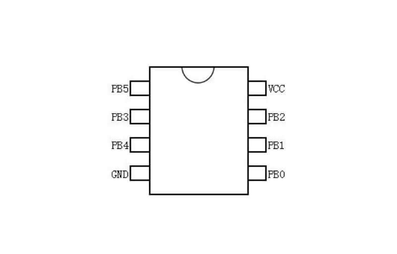
- Pin1 (PB5): The functions of this pin are PCINT5, ADCO, dW, and RESET. This pin serves as an analog, reset, boot loader, ADC, and delete.
- Pin2 (PB3) : The role of Pin2 is XTAL1, CLKI, ADC3, OC1B & PCINT3. pin2 is mainly applied for USB programming, XTAL input, analog input and PWM.
- The main functions of Pin3 are XTAL2, CLKO, ADC2, OC1B and PCINT4. This pin is primarily used for analog inputs, USB programming, PWM, and XTAL outputs.
- Pin4 (GND): Pin4 introduce ground or negative power to the system.
- Pin5 (PBO) : The main functions of Pin5 are AINO, MOSI, OC1A, OCOA, DI, AREF, SDA and PCINTO. It take charge of SPI communication, PWM output and 12C communication.
- Pin6 (PB1) : The main functions of Pin6 are MISO, AIN1,OCOB, OC1A, DO and PCINT1. Pin6 is used for PWM o/p, SPI data o/ P.
- Pin7(PB2)The main functions of Pin7 are SCK, ADC1, TOm SCL and PCINT2. Pin7 is mainly used for SCL and SCK of analog i/p and SPI data.
- Pin8 (VCC): Pin8 is used to provide voltage supply to the system.
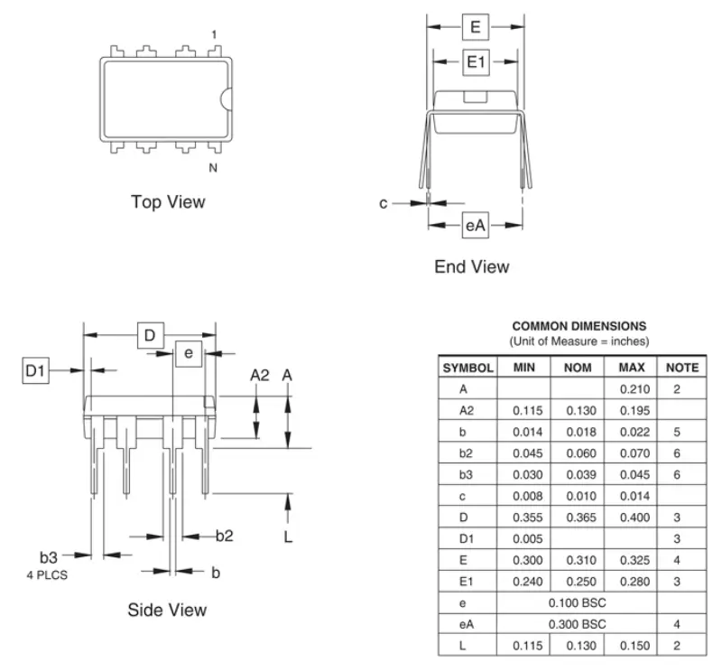
What is the size of ATtiny85?
Features & Functions & Application
ATTiny85 distinguish other ICs by many advantages. First, lower cost and less power consumption make it friendly to the users and environment. Second, due to its small and compact size, it can be easily arranged in a small PCB board. Third, it is capable of working with battery-powered application programs by different power saving modes. Fourth, many functions are embraced by small pins, so it takes a full use of space when it’s used in small and high-tech PCB. Last, its program memory is not bad.
ATtiny85 is a very advanced micro-controller that includes several functions, so it can be used in a variety of electronic applications. This micro-controller just like a small Arduino. Once the code is small and alternative controller is required, then the ATtiny85 is the right choice.
It is widely applied in different fields, such as automotive, industrial control, sensor system, solar energy device, telecom, medical device, IoT, embedded system and even robot field.
What Is the Differences Between ATtiny84 and ATtiny85?
They are different in the pin configuration. ATtiny comes with 8 pins. Five of them is suitable for digital I/O. Three of them can serves analog input. Two of them can be PWM pins. In contrast, ATtiny84 has 14 pins. Eight of them is available for digital output and analog input. Three is capable of PWM output. What’s more, its PB7 pins also supports PWM.
What Is the Differences Between ATtiny13A and ATtiny85?
Compared to ATtiny13A, the 85 has more flash, RAM and EEPROM memory. Also, Attiny85 is easier to get started than 12A since it has more libraries available.
A Closer Look at ATtiny85 Family
| Item | Brand | Description |
| ATTiny85-20PU | Microchip | AVR, 4KB FLASH, 256B SRAM, ADC, 2 TIMERS – 5V, 20MHz, PDIP, IND TEMP, GREEN |
| ATTiny85-20MUR | Microchip | AVR, 4KB FLASH, 256B SRAM, ADC, 2 TIMERS – 20MHz, QFN/MLF, IND TEMP, GREEN, 5V, T&R |
| ATTiny85-20SF | Microchip | AVR, 4KB FLASH, 256B SRAM, ADC, 2 TIMERS – 5V, 20MHz, SOIC, +125C, GREEN |
| ATTiny85-20SU | ATMEL | MCU 8Bit ATtiny AVR RISC 8KB Flash 3.3V/5V 8Pin SOIC EIAJ |
| ATTiny85-20PU | ATMEL | 8Bit Microcontroller, Low Power High Performance, ATtiny, 20MHz, 8KB, 512Byte, 8Pins, DIP |
| ATTiny85-20MU | ATMEL | AVR, 4KB FLASH, 256B SRAM, ADC, 2 TIMERS – 5V, 20MHz, MLF, IND TEMP, GREEN |
| ATTiny85-20SH | ATMEL | 8Bit Microcontrollers – MCU 8K FLSH 256B EE 512B SRAM ADC 5V 20MHz |
| ATTiny85-20SUR | ATMEL | MCU 8Bit ATtiny AVR RISC 8KB Flash 3.3V/5V 8Pin SOIC EIAJ T/R |
| ATTiny85-20MUR | ATMEL | AVR, 4KB FLASH, 256B SRAM, ADC, 2 TIMERS – 20MHz, QFN/MLF, IND TEMP, GREEN, 5V, T&R |
| ATTiny85-15SZ | ATMEL | MCU 8Bit ATtiny AVR RISC 8KB Flash 3.3V/5V Automotive 8Pin SOIC |
| ATTiny85-15ST1 | ATMEL | MCU 8Bit ATtiny AVR RISC 8KB Flash 3.3V/5V Automotive 8Pin SOIC |
ATTiny85 family contains many items to meet your accurate requirements.
Where to Purchase ATTINY85| Be Buying
When we are buying ATTiny85, one of the better ways is to turn to its original factory or distributors.
Top 5 ATTNY85 Seller
- Microchip: Microchip Technology is the original provider of ATtiny85. It also offers outstanding technical support.
- Mokotechnology : Mokotechnology is your trusted electronic manufacturer. It offers ATtiny85 and the whole solution of any PCB design with it.
- Mouser Electronics: Mouser Is an Authorized Distributor of All the World Leaders in Electronic Components.
- Digikey: World’s Largest Selection of Electronic Components Available for Immediate shipment, capacitors, resistors for any design or device.
- RS Components: RS is the online leading provider of industrial and electronic solutions. Secure online ordering, same-day dispatch & free delivery available.
How to Use ATtiny85 with Arduio?| After Buying
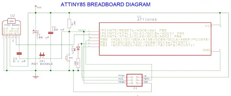
Ttiny85 ISP is an open-source device with Arduino IDE compatibility. Here we take one of using case, mini USB, to show you how ATtiny85 uses in consumer electronics.
This design uses an internal 8 MHZ clock to drive the microcontroller. To transfer data to the FTDI board, pin 2 of the microcontroller is connected to the TX pin of the FTDI board. FTDI splitter on pin 3 offer 5V-powers to the microcontroller. Jumper JP1 is used to enable/disable resetting micro-controller when establishing terminal connection with FTDI splitter board.
When debugging sketches with AVR Dragon, don’t forget to turn on jumper JP1. Otherwise, capacitor C3 will cause side effects when stepping code.
How to Program ATtiny85?
You can use Arduino Uno to program ATtiny85.
Step 1: We first need to configure the Arduino Uno as an ISP to act as the programmer for the ATtiny85. To do this, connect the Arduino Uno to your laptop and turn on the Arduino IDE. Then, click file >Example>ArduinolSP and upload the Arduino ISP code.
Step2: Program ATtiny85 circuit diagram.
Step3: Program it by the Arduino IDE.
How to Run ATtiny85 Carefully?
It is a very sensitive component. To get the best performance from controllers over the long term, designers should be careful when using them in any application.
- Supply voltage should not exceed 5.5V. And the output of the voltage source needs to be verified by an accurate digital multi-meter before connecting.
- The DC of each 1/0 pin should be 40mA. The GND pin and positive power supply should be 200mA. Before power is supplied, the polarity of the micro-controller pin should be verified.
- To position this controller, you need to use an IC socket on the circuit or breadboard that protects the controller from the heat generated during welding.
- In addition, the minimum and maximum storage temperature is -65°C to +150°C, but the operating temperature is -55°C to +125°
If you have extra question on ATtiny85, such as embedded design and related device manufacturing, please feel free to contact us.